with Flying Leathernecks plastic tail boom access panels and Werner’s Wings decals, resin rotor base, resin ARC-102 antennae mounts and Italeri main rotor blades
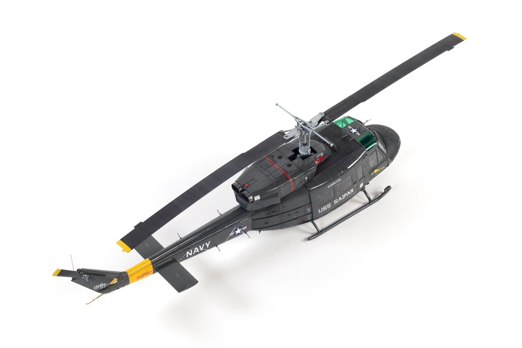
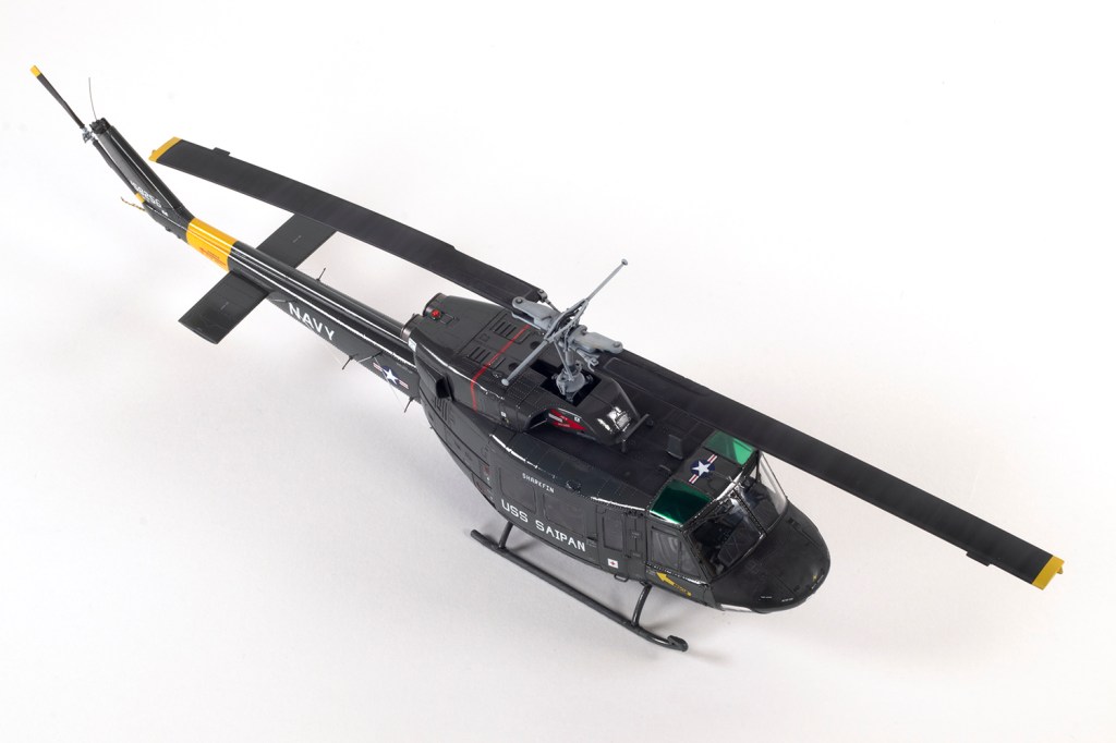
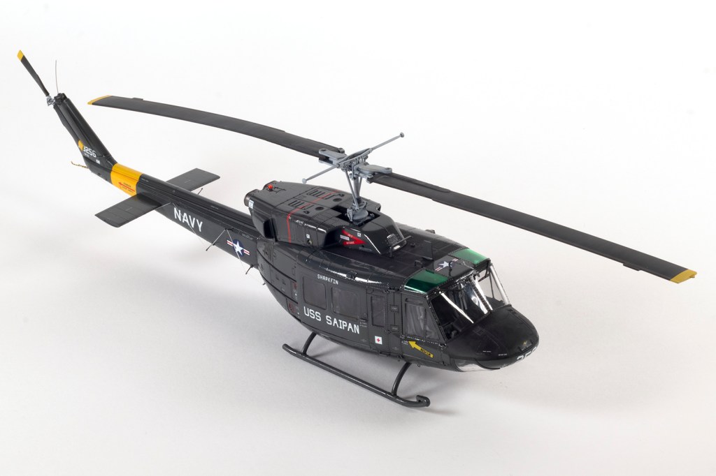
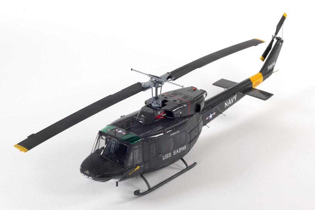
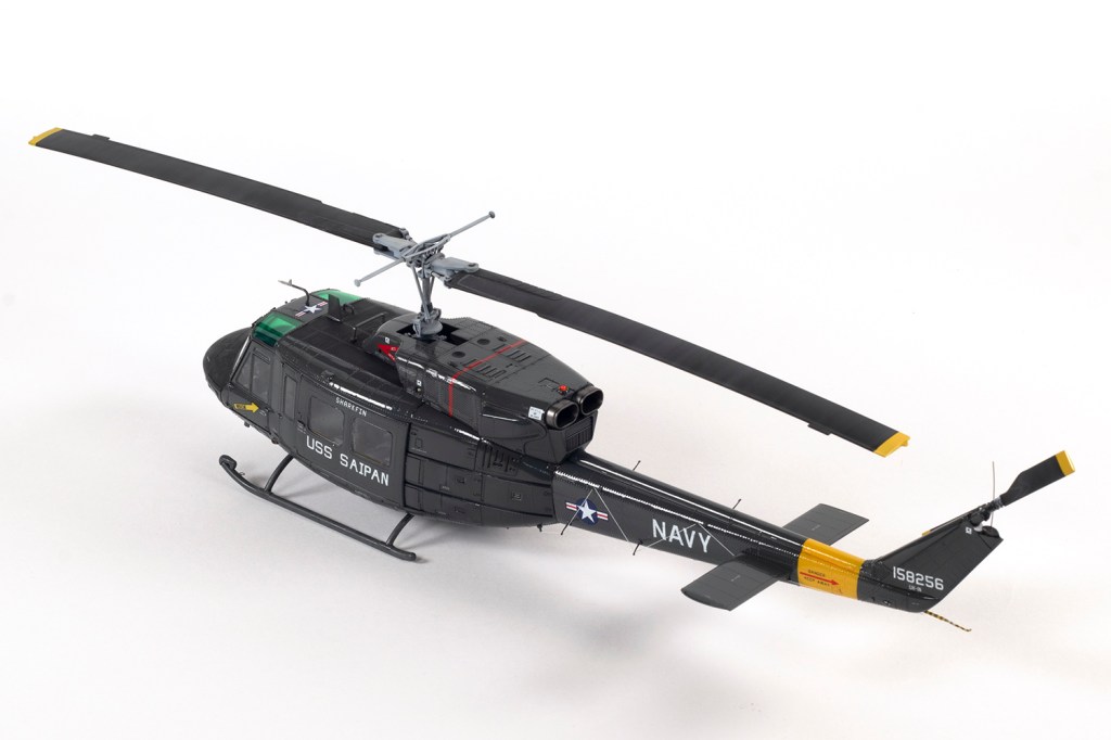
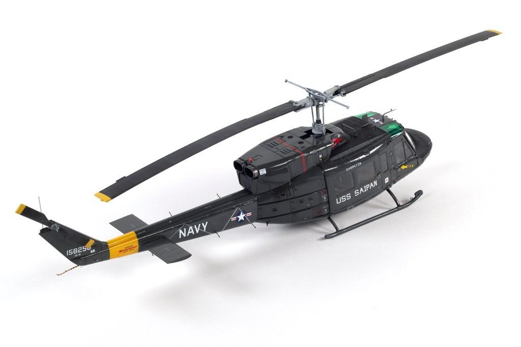
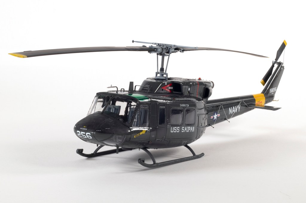
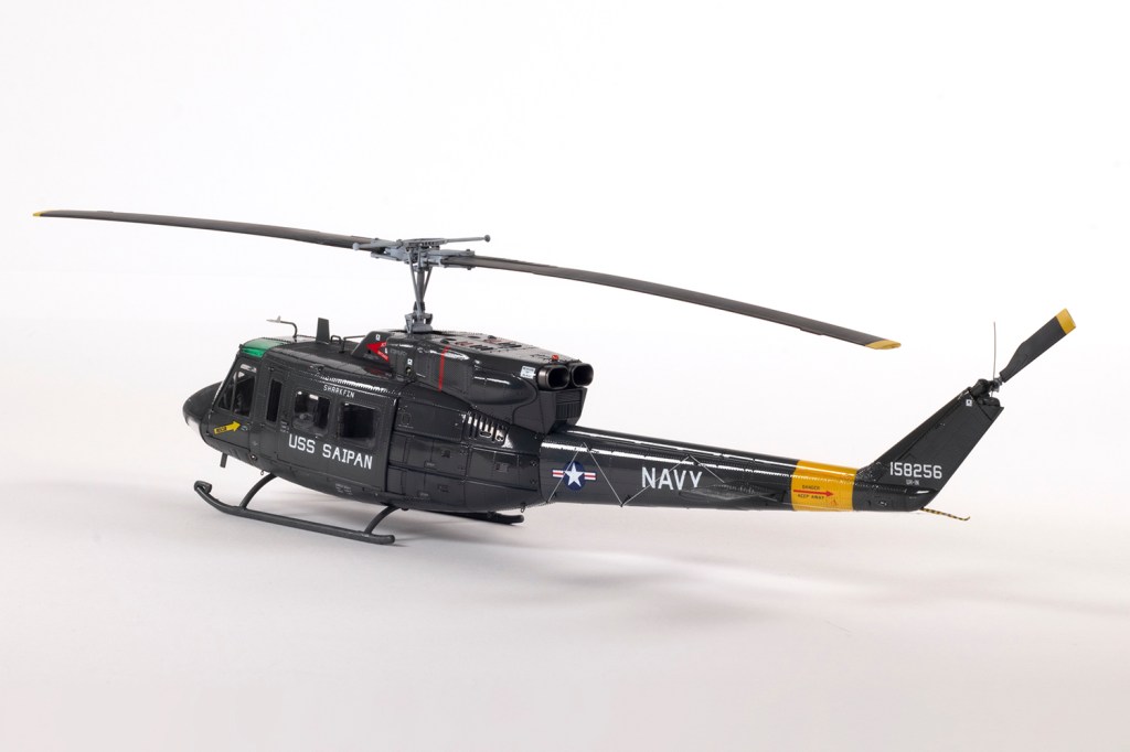
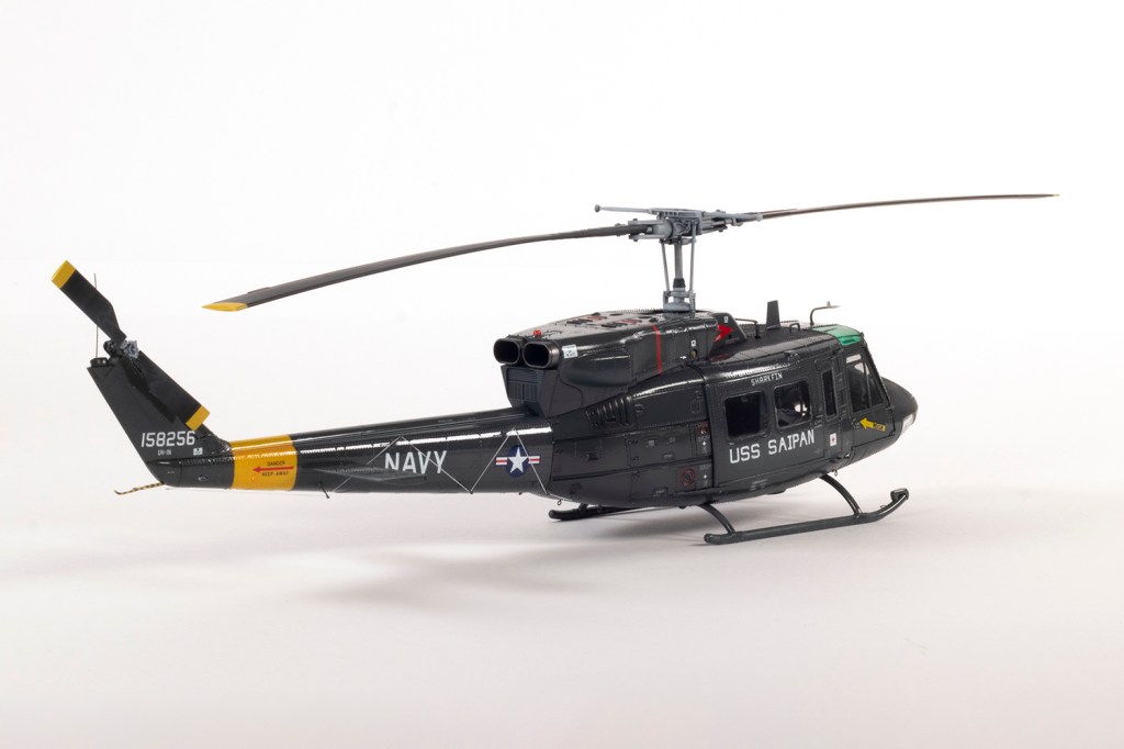
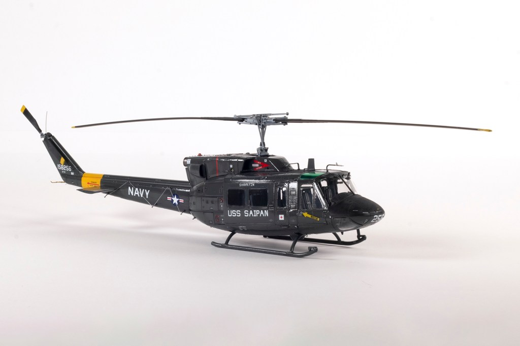
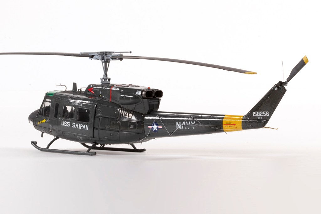
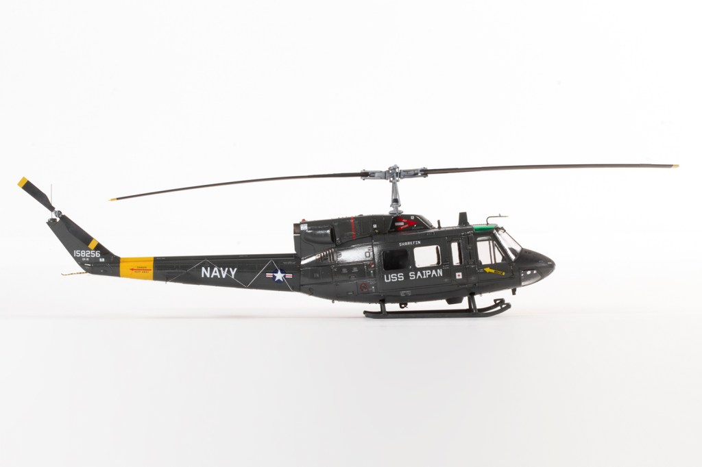
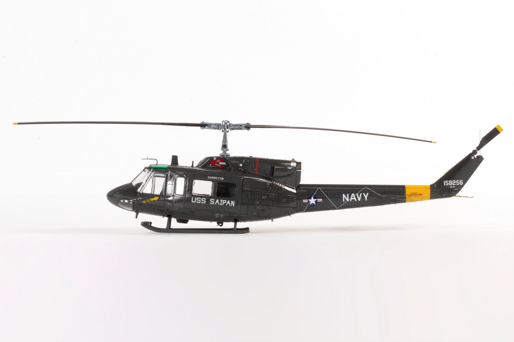
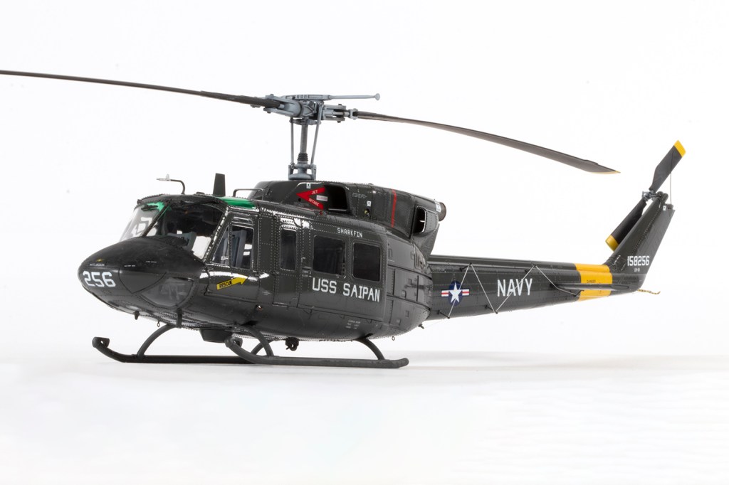
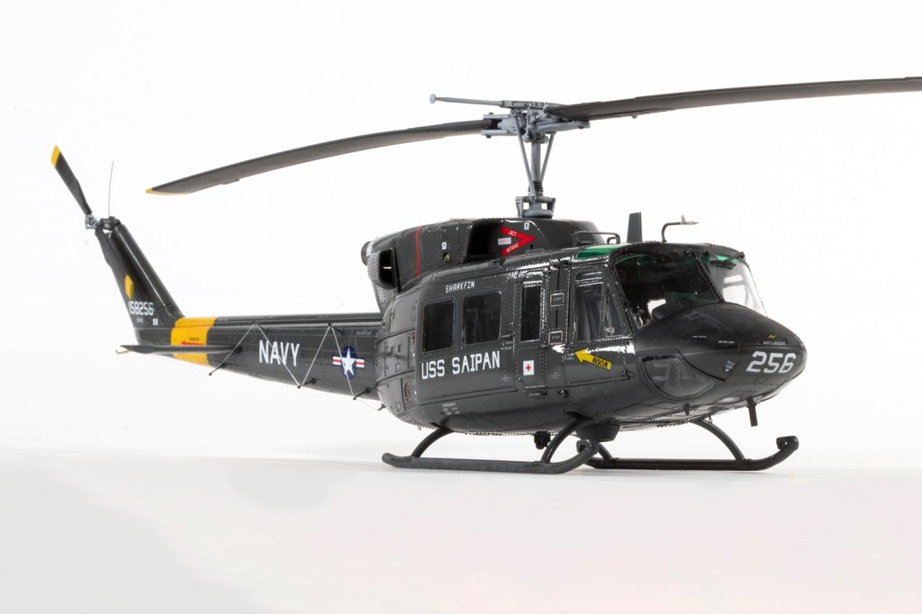
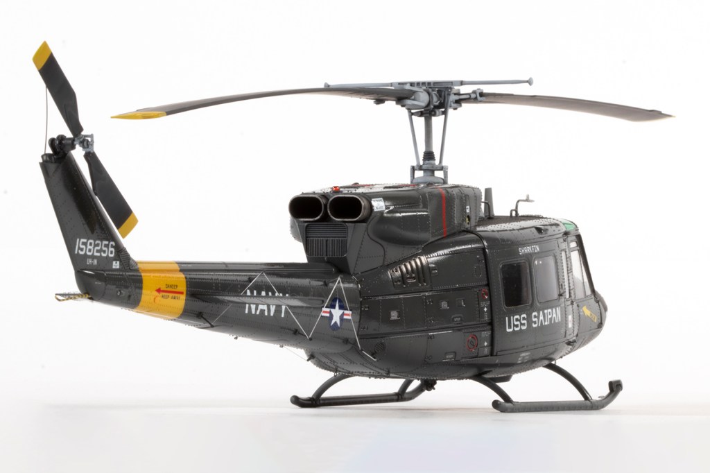
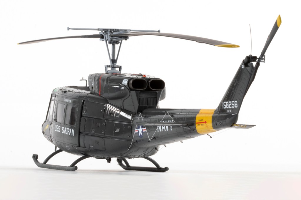
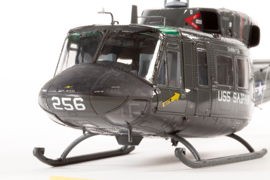
US Navy, USS Saipan 1986
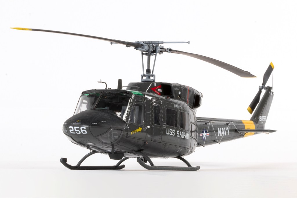
I’d been attracted to the Kitty Hawk 1/48 UH-1N for a long time on account of how gorgeous US Navy helicopters look in the glossy Engine Gray colour scheme shown in the box art, but the inaccurate rotor blades had put me off. A Temu advert on Facebook, however, reckoned I could get it for £12.47 including postage. I was sceptical, but willing to take a risk, and with PayPal you can always get your money back anyway, plus it added to the excitement: what would actually arrive in the post?
What did arrive was exactly as advertised: a perfectly packaged brand new kit with everything included. So there you are: a new 1/48 helicopter with resin crew figures and a sheet of PE in 2025 for under £13 all in. Miracles do happen.
Kitty Hawk were masters of marketing, and the lovely box, colour instructions and multiple decal options lure one in. And to be fair, it is a good kit which I thoroughly enjoyed making, but beware! All is not as it seems…
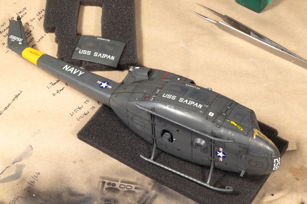
The first issue is that I really wanted to make that glossy Engine Gray Twin Huey shown on the box, but the kit doesn’t really want you to, at least not without a lot of modifications. The UH-1N was used by a number of operators in a host of roles, and despite all the decal options included in the box, the kit is set up for you to make a late-model US Marines Twin Huey. To make a US Navy ship-borne example from the mid-80s required a keen eye and sharp wits. So let’s begin.
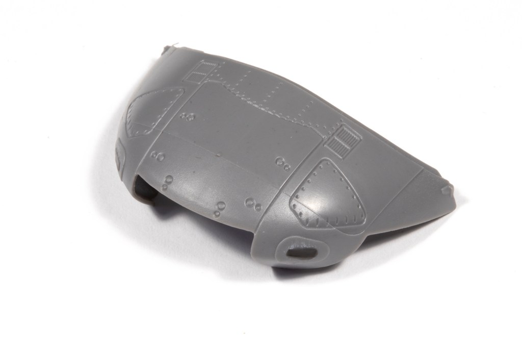
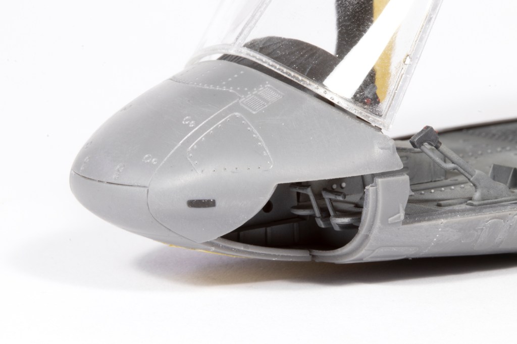
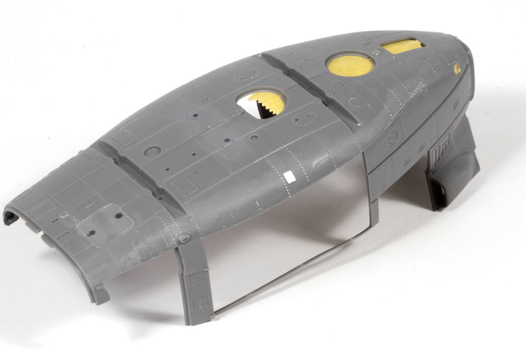
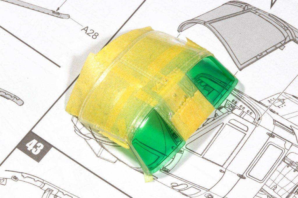
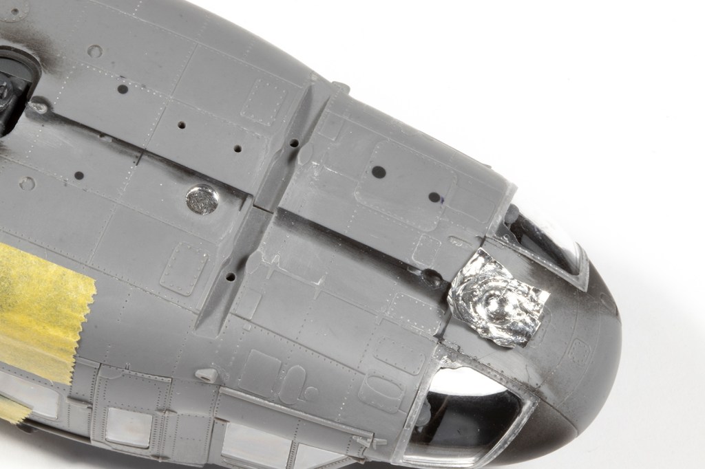
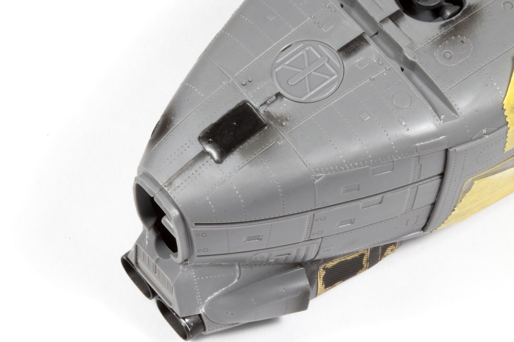
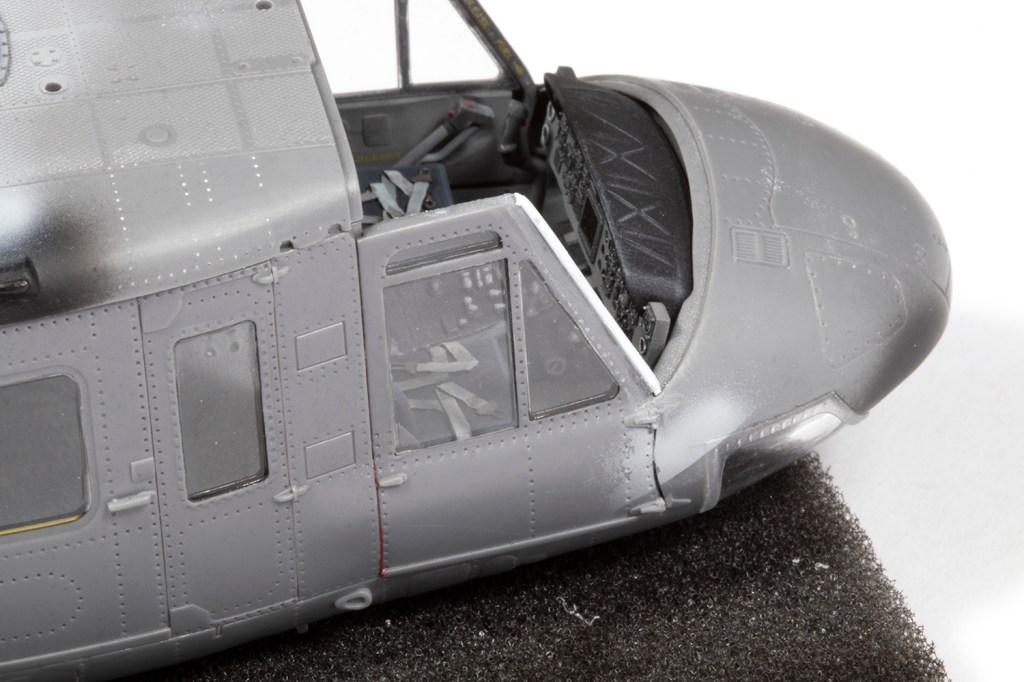
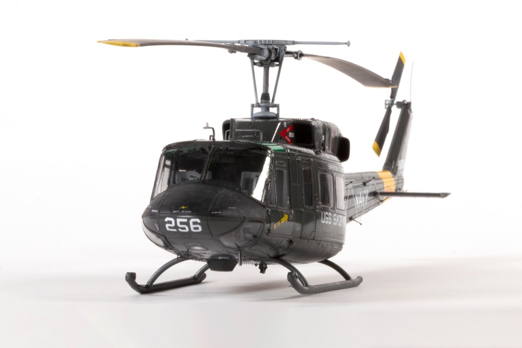
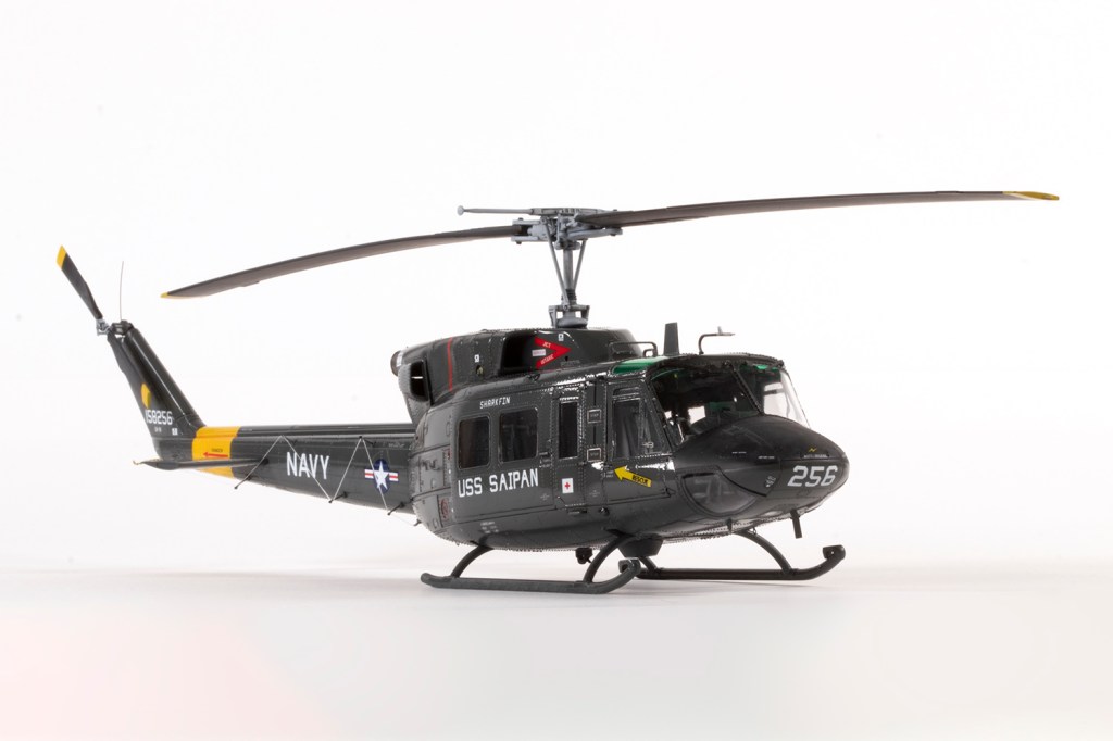
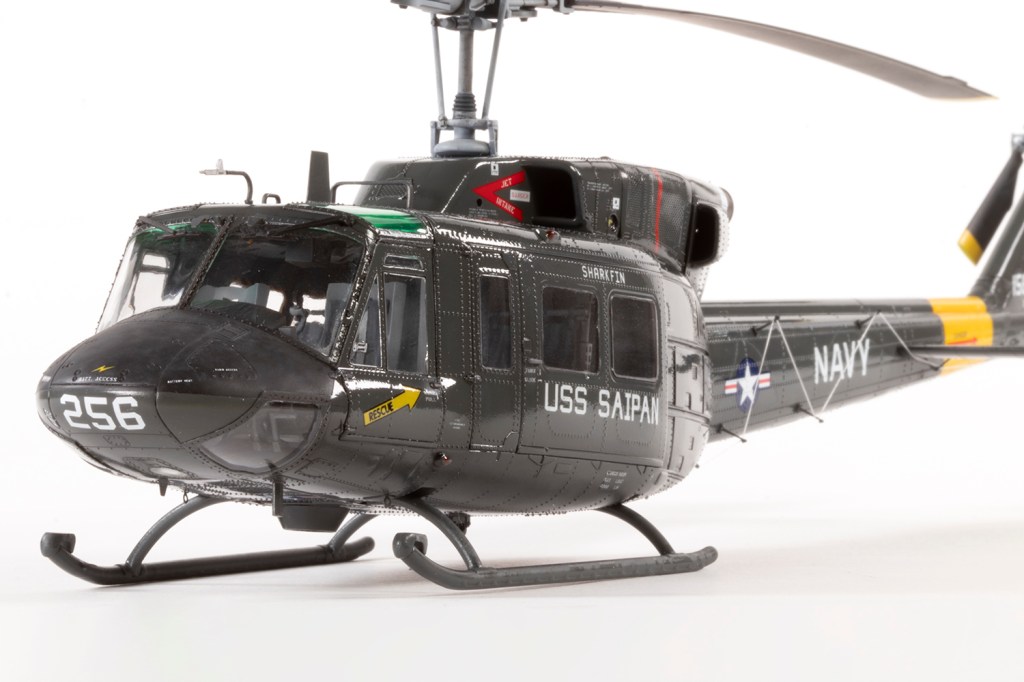
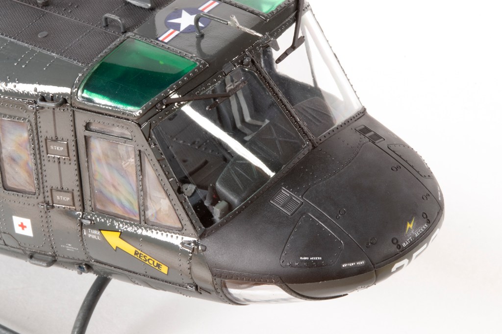
From the nose, the nose is wrong. Fortunately, the correct part is on the sprues, but not mentioned in the instructions. Unfortunately, there is no transparent part for the light mounted in said nose, so you’re on your own there. I used clear UV resin over Bare Metal Foil. Parts B72 and B73 (nose-mounded sensors) can be omitted, and the plates they attach to sanded off the nose.
All the wire cutters can be ignored, and all the slime lights shaved off. Don’t bother adding parts B49 and B50 to the side of the windscreen. Under the fuselage, parts D37 and B63 are not applicable, and whilst B65 is, you will have to chop off at least some of the locating pegs for which there are no holes (a Kitty Hawk trait that raises its ugly head several times during the build – check everything!). An extra blade aerial under the front port side of the nose needs to be sourced from somewhere; mine came from a Hasegawa A-4 kit.
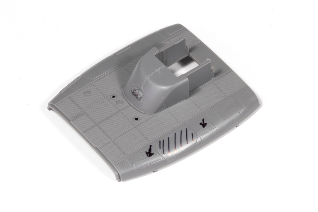
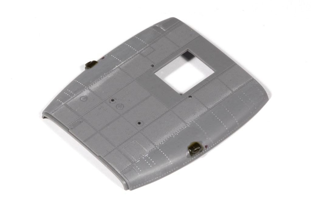
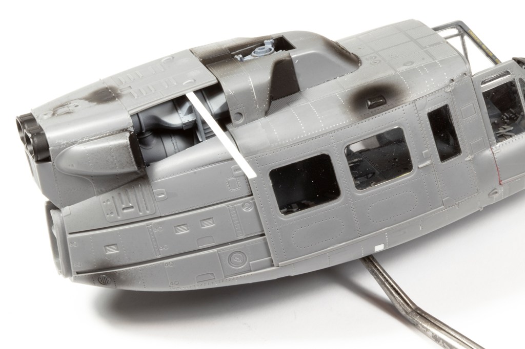
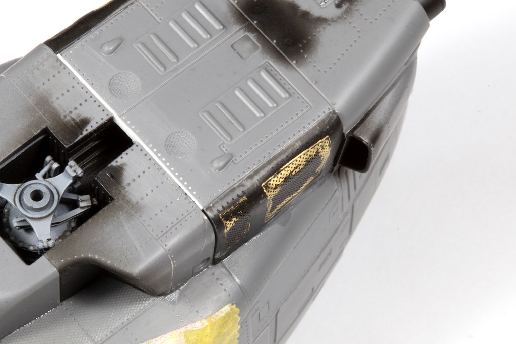
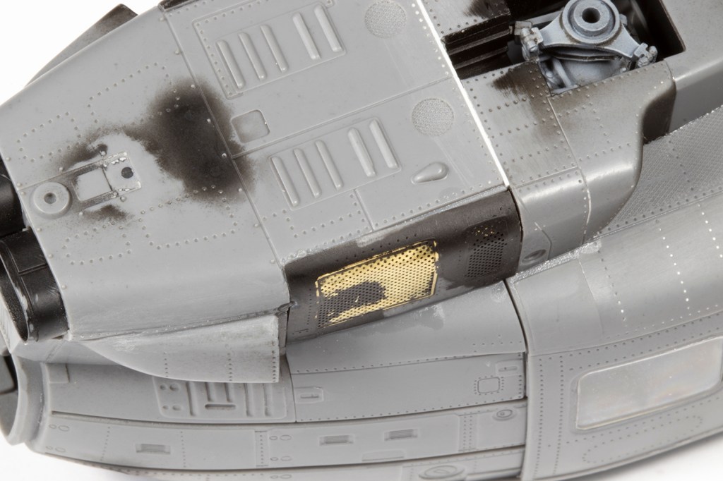
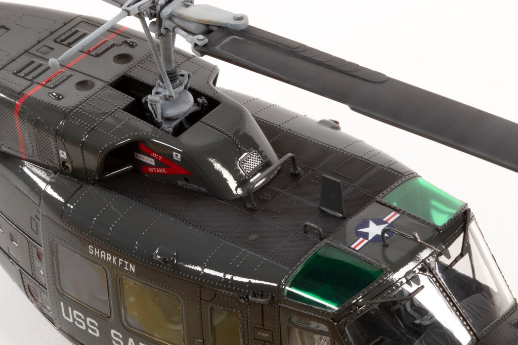
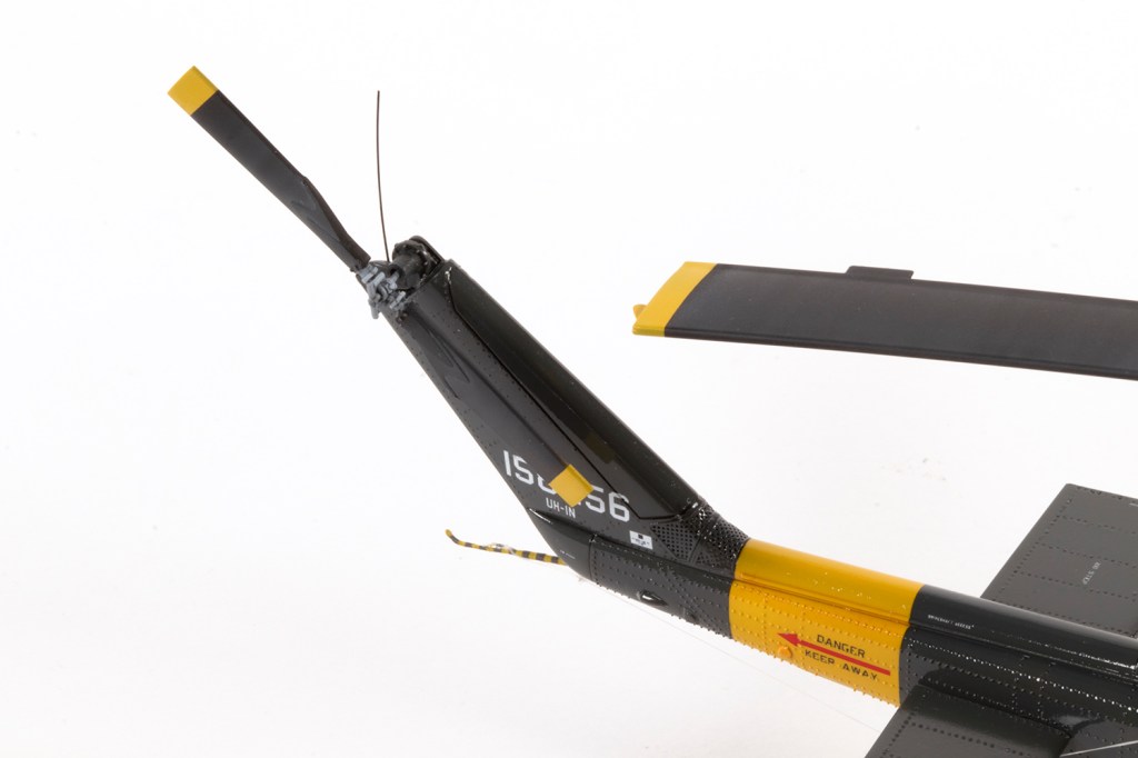
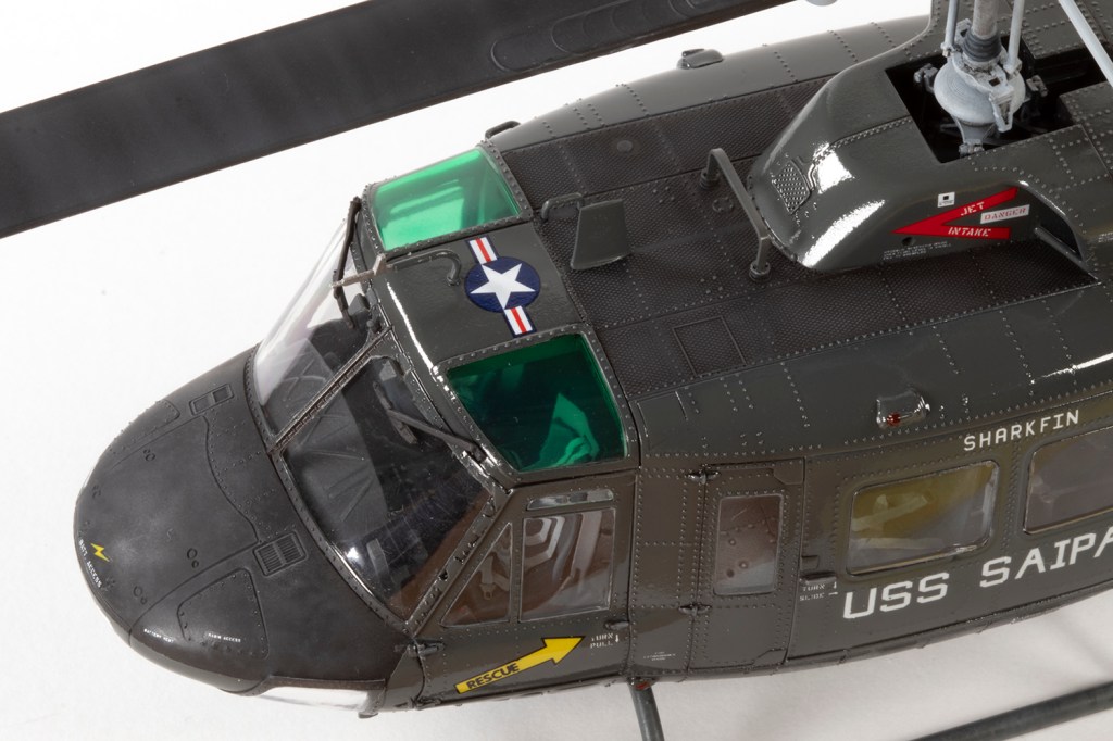
Many more parts can be omitted from the roof: B11, B10, D25, D20/B84, D30, D5 and D6, and respective mounting points moulded on the fuselage halves can be sanded off. Plenty of armament is provided and was immediately consigned to the spares box, but this means the holes under the main cabin doors where ammunition belts feed through ought to be filled. Towards the rear of the upper fuselage, parts B74, B75, B76 and B2 are not required, and the transparent light replaced with the smaller one from the clear sprue. On the tail the chaff buckets aren’t needed, but the parts are thankfully different to what’s shown in the instructions and so only the slime lights need removing. I could also chuck parts B7 and B6 in the spares box, as well as C48, but the latter were usually fitted, just not on the helicopter I was modelling.
Add in the need to fill in the hole created by part B13 under the rear fuselage, and I think that covers most of it. There are plenty of high quality photos of these airframes available on the net, and Google is your friend.
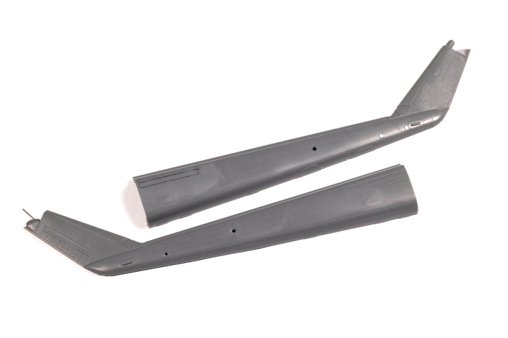
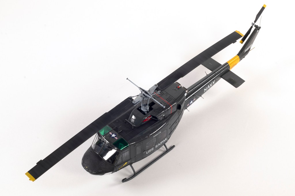
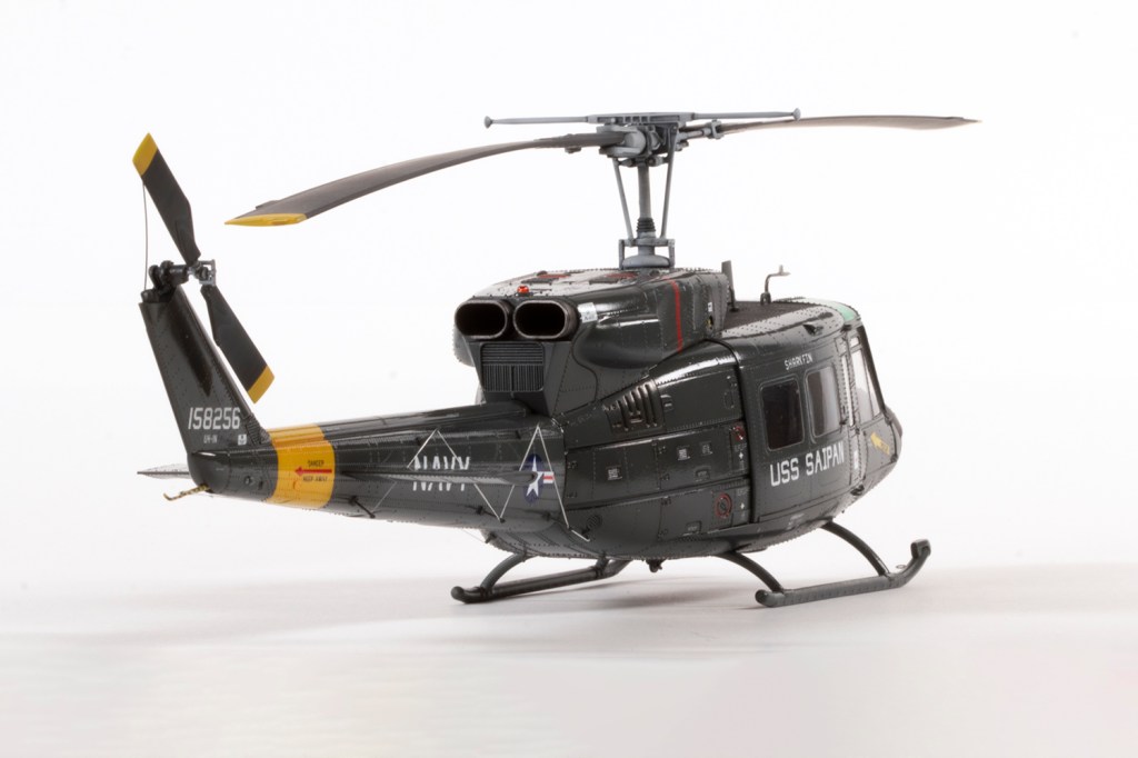
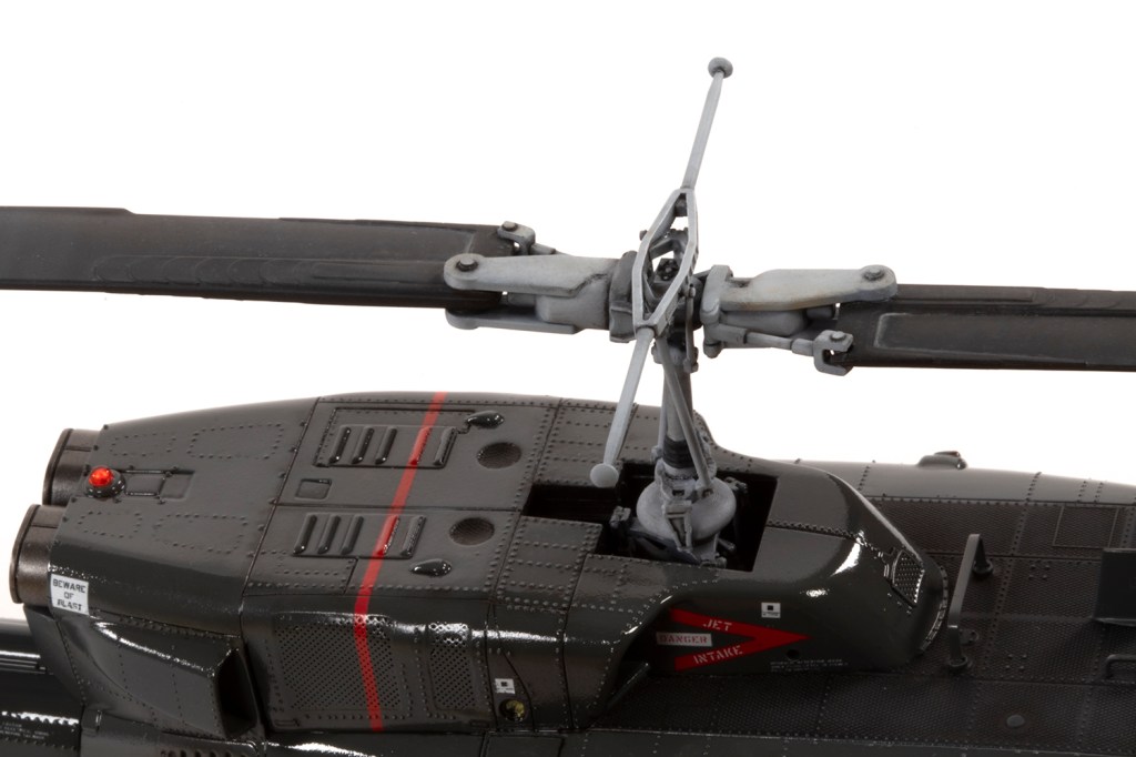
The second issue is that whilst Kitty Hawk made a genuinely admirable effort to cater for the changes from their earlier UH-1D (and thus there are tons of unused parts), they fell somewhat short on the rotor blades, which are just lifted from the single-engine Huey. Twin Huey rotor blades were wider in chord. Fortunately, Italeri (and equivalent Revell boxings) got it wrong in exactly the reverse direction: their UH-1N blades are accurate, but also included in their UH-1D kits. Legendary helicopter modeller Ian McGonagle did me a huge favour and gave me a Revell (Italeri) UH-1D from which I could rob the blades. Whilst I had it, I also robbed the navigation lights above the main cabin doors, since Kitty Hawk didn’t need these for its late-model UH-1N as massive sensors sit here instead.
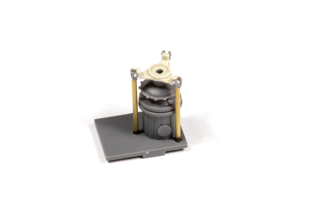
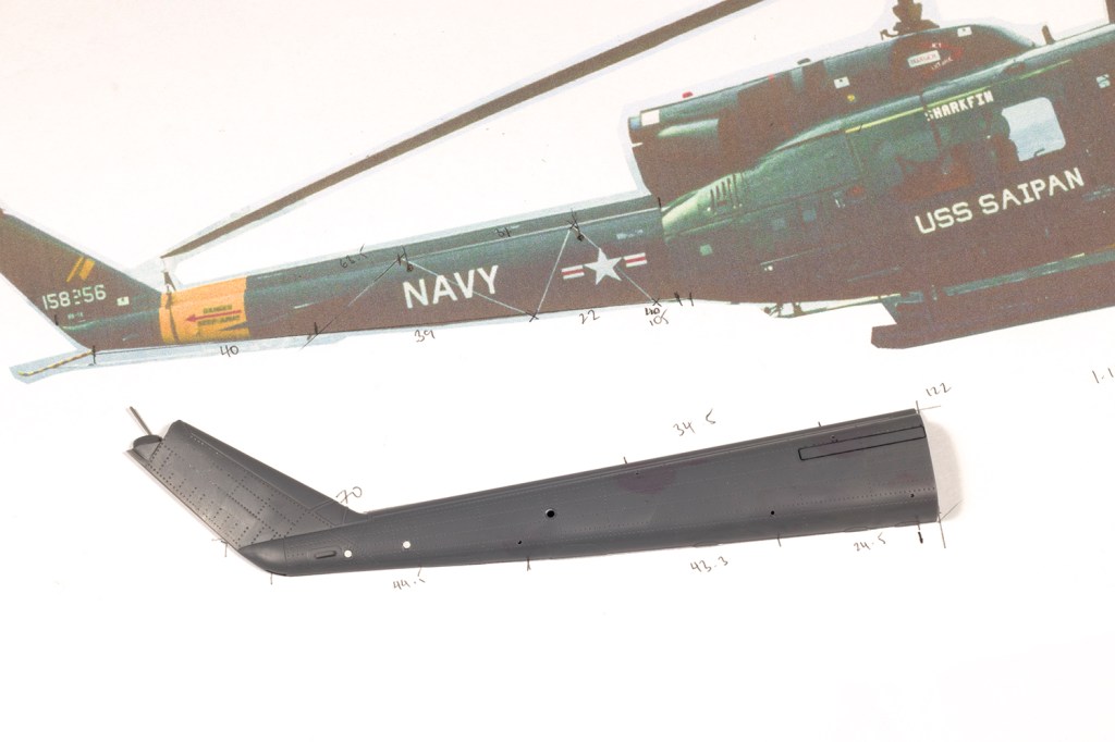
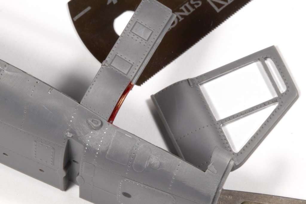
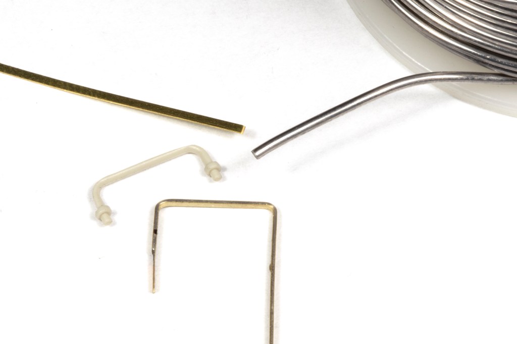
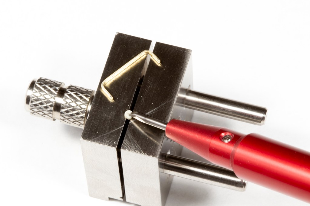
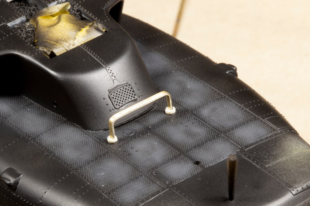
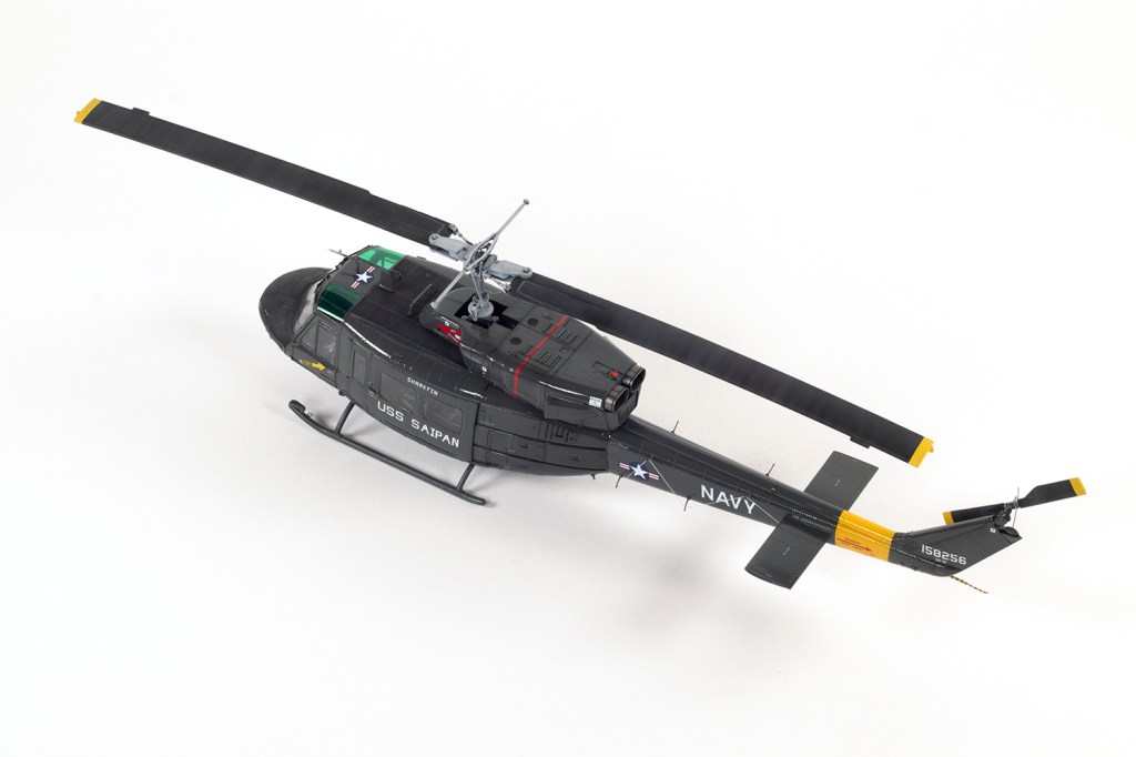
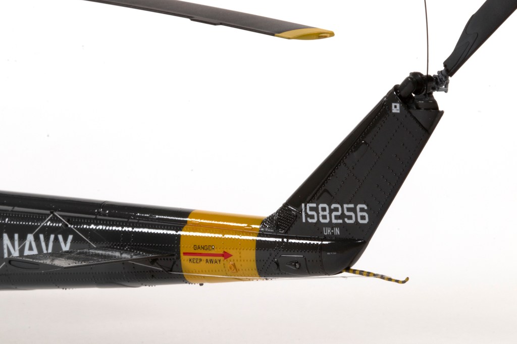
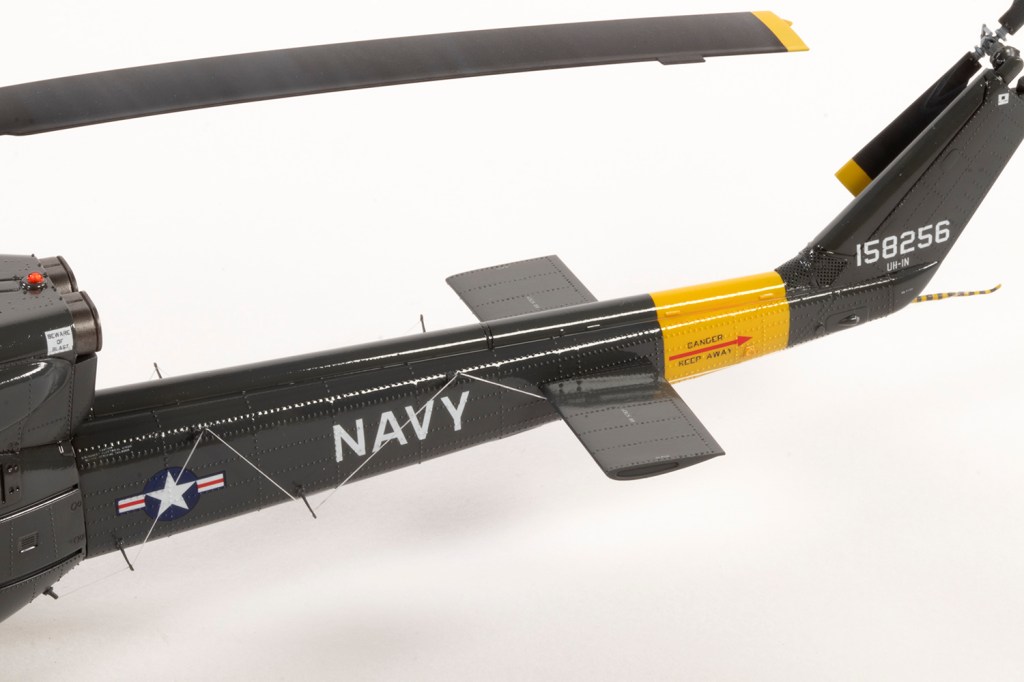
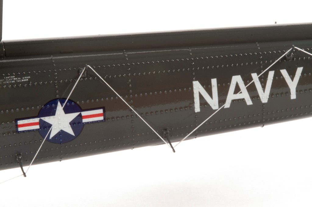
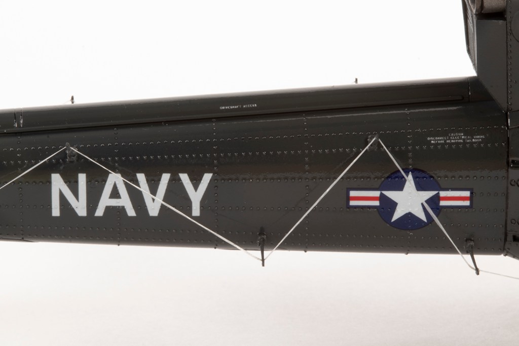
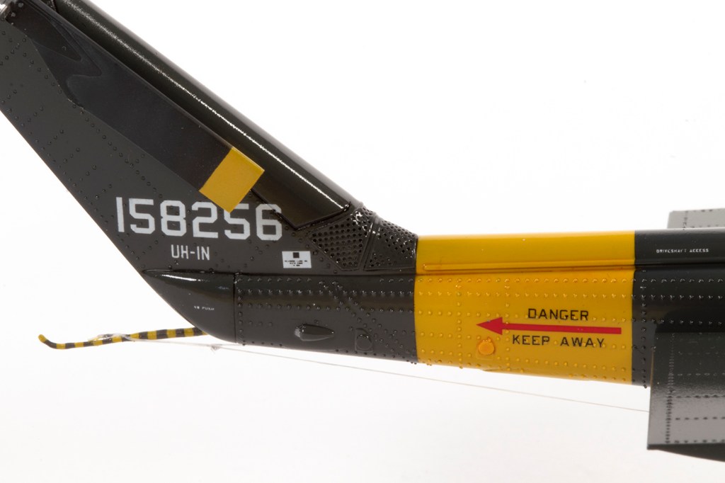
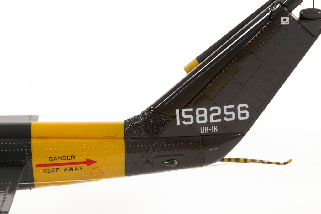
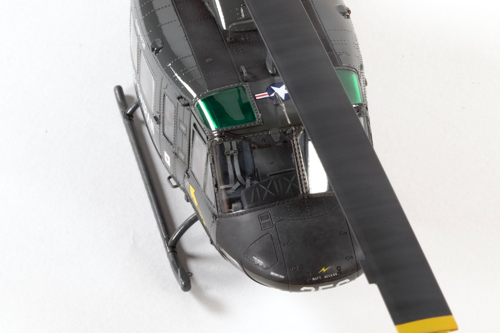
The third issue is that these Twin Hueys (and many others) were fitted with the ARC-102 HF radio wire strung between prominent posts down the tail boom sides. This aerial is usually white, and often not tensioned, and a very striking feature of the airframe I had chosen to model. Fortunately, Werner’s Wings did me a great deal and shipped a couple of sets of their 3d-printed antenna posts. The set comes with some white EZ-line, but I thought it was a little thick and replaced it with some white 0.1mm elastic fishing line purchased on Amazon. Annoyingly, I didn’t quite measure out the post locations right, and so the wire is slightly fouled by the elevators, and the sharp-eyed might notice that one of the posts right at the back collapsed before the photos were taken.
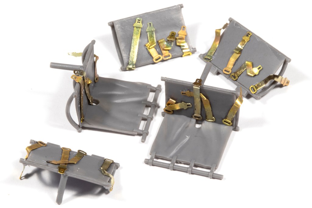
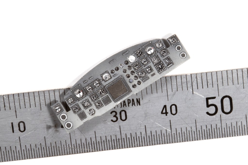
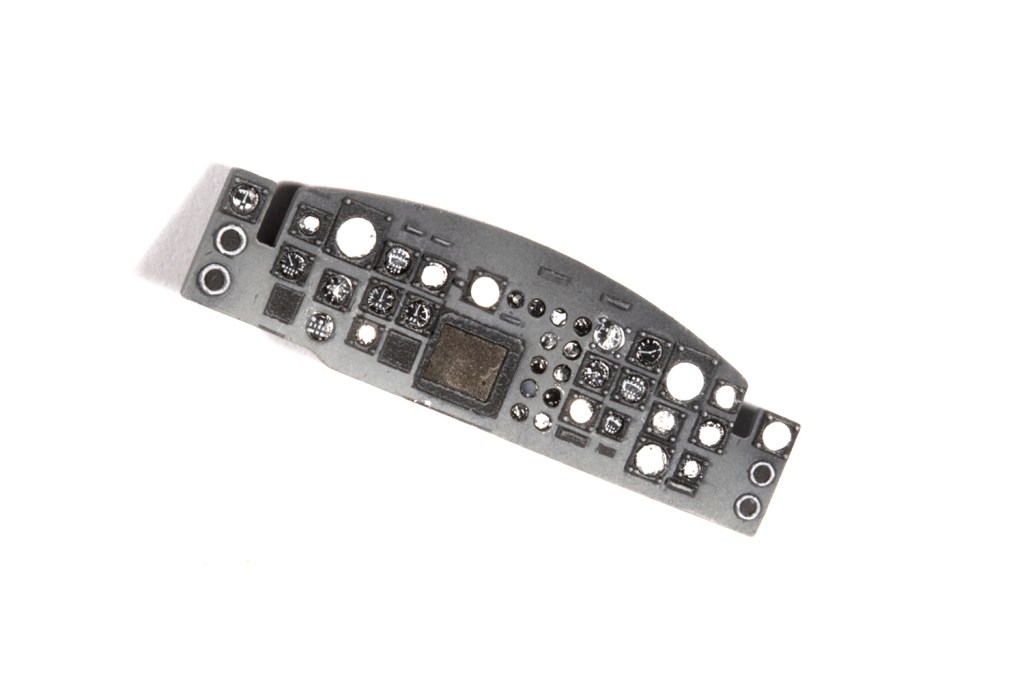
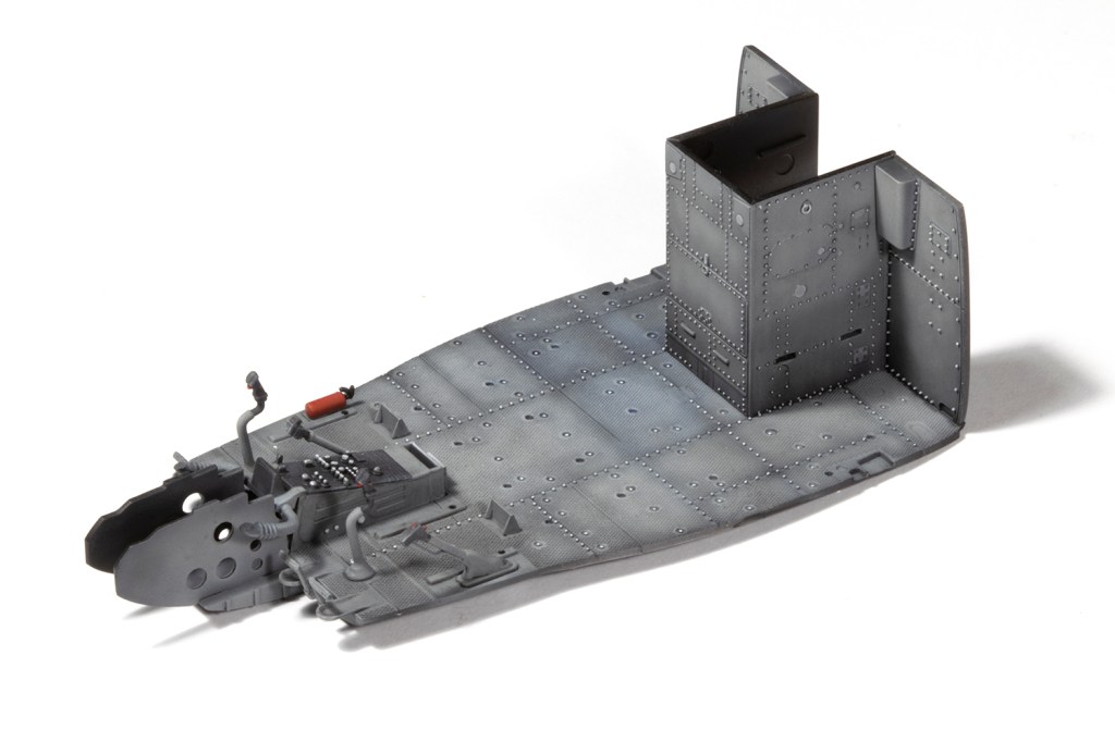
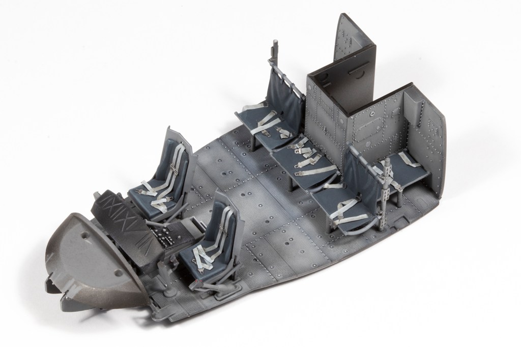
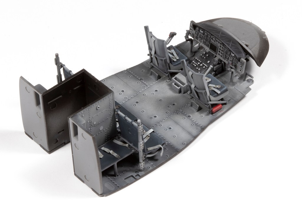
Prior to making this kit, I made the Kitty Hawk UH-1H with all the ResKit interior and open doors, so it was nice to do a more cursory job on the inside of this one and shut everything up. It has to be said that what comes in the box for the cabin is lovely, although the PE belts for the front seats don’t make a lot of sense, and those in the rear don’t have much to attach to. Never mind, it’s way more detailed than it needs to be given I was closing the doors, but good fun to make up and paint.
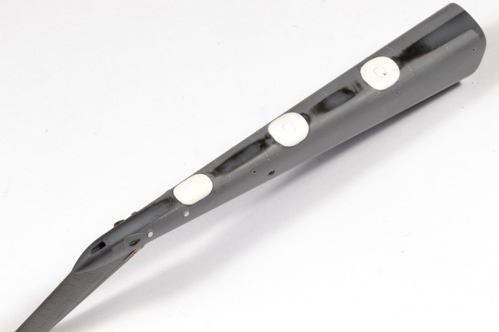
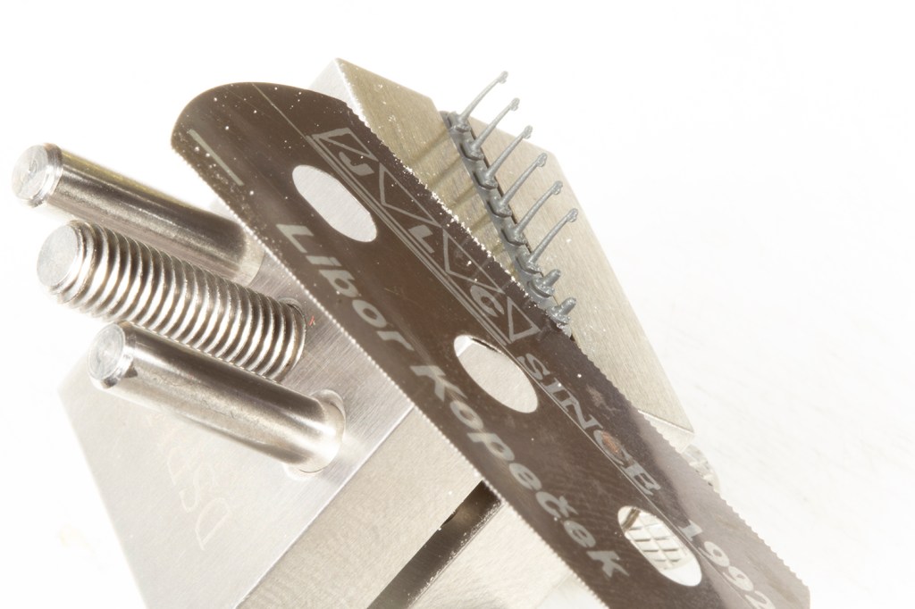
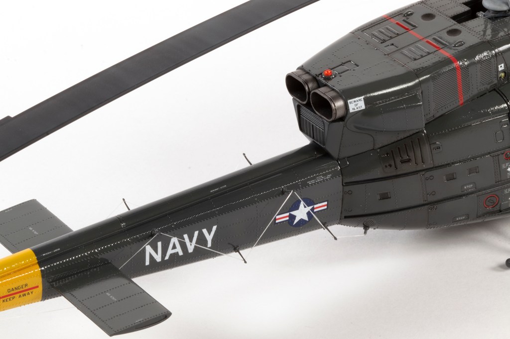
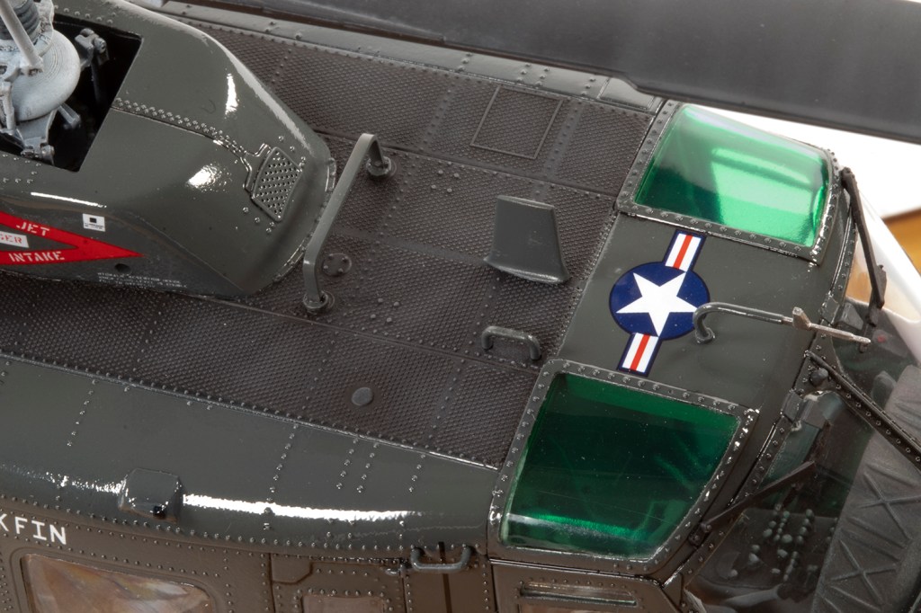
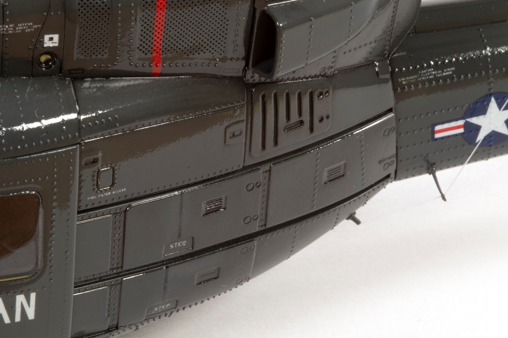
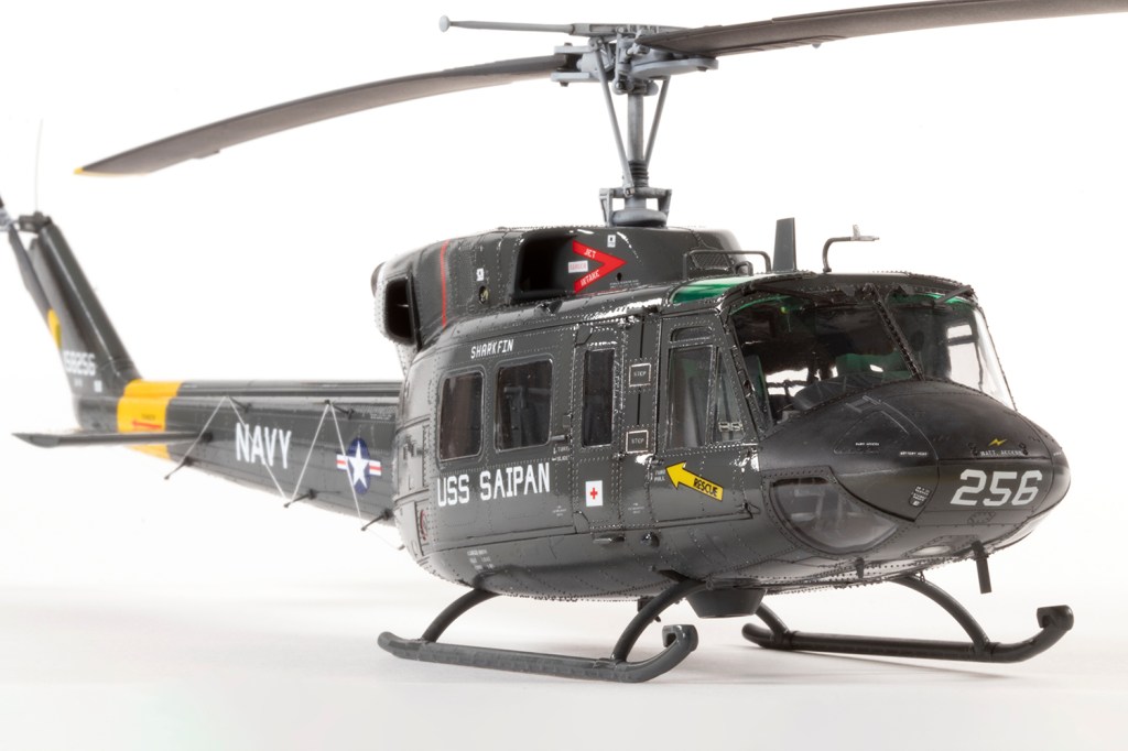
Aside from all the previously mentioned modifications, the other central focus of this build was going to be the rivets. Sometimes I see a modeller using a particular technique and I think it’s bonkers, which is usually a sign that I will inevitably adopt it in due course, and that’s what happened here.
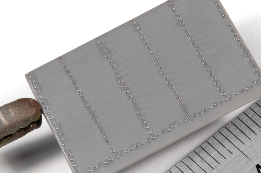
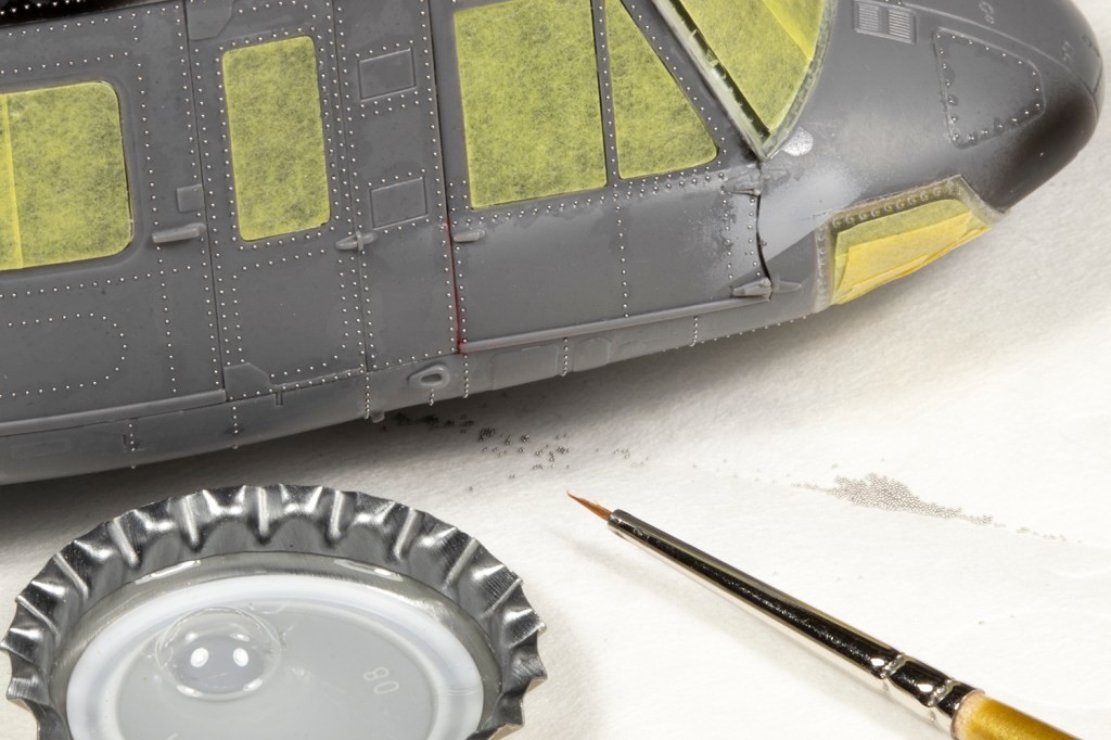
A few years ago I saw the peerless French aircraft modeller Fanch Lubin using 0.3mm solder balls to replicate positive rivets on a 1/35 Kitty Hawk H-60. The technique looked simple in concept: fill each moulded negative rivet with a little ball to represent a positive one. Loads of more recent helicopter toolings have negative rivets, just because they’re easier to work with, even when the real thing was festooned with positive rivets. The technique looked mad, and I was intrigued.
Last October I was at Scale Model Challenge in the Netherlands and came across Andy Evans, who was doing the same thing on his 1/35 H-60. He was using slightly smaller balls (0.25mm) and Johnson’s Klear to glue them in. He convinced me it was very therapeutic and quite feasible. I knew I was going to have to try.
And try I did, on the aforementioned UH-1H, but I discovered 0.25mm is just still too big and that 0.2mm (which was the smallest size of solder ball I could reasonably obtain on eBay) was better still. It was successful enough I wanted to do it again here.
My method is simple: I tip out a few of the solder balls on some paper. I have a small capful of fresh Johnson’s Klear to hand, and a very fine cheap brush. Using the brush I dab a titchy amount of clear in the rivet hole, and then using the same brush I can pick up a solder ball and pop it near the hole. It will generally then wick into the hole. In some areas, several holes can be filled in one go. This sounds insane, but it really doesn’t take as long as I thought.
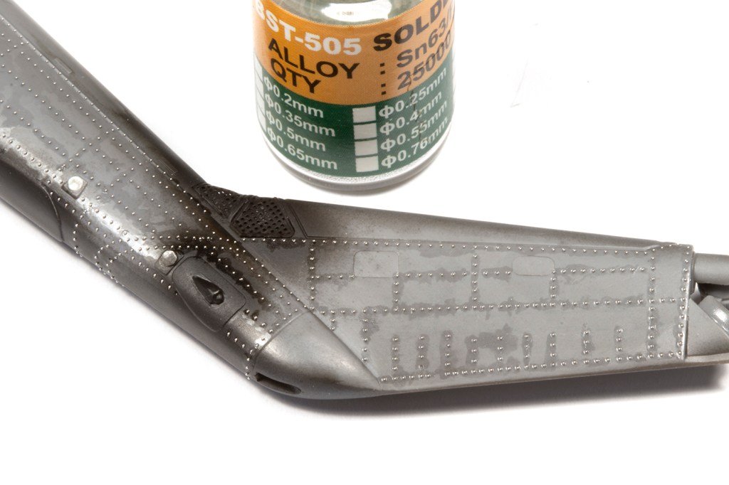
The Klear needs to be fresh so it dries as thin as possible. If it gets even slightly thick, its stands too proud of the surface. Yet even with fresh Klear, when it dries it’s still visible under a thin layer of paint, and looks very ugly. To solve this, I paint as normal and then over that spray a very generous layer of VMS Matt Varnish, which must be applied thick and wet. This will magically make the effects of the Klear disappear, and the surface will be gloriously smooth.
There are pitfalls to riveting in this fashion. Klear is not a strong adhesive, and balls will fall out during handling and, occasionally, masking. The rivets are made of solder, and paint will rub off them easily. And even with 0.2mm balls, the rivets are massively overscale (9.6mm in real life), but then in 1/48 all surface detail is overscale. You’ll also need to get the decals to conform over them…
Despite all this, I found it extremely rewarding and I definitely intend to do it again for future helicopters where appropriate. However, unlike my UH-1H, which looks wonderful in VMS Matt Varnish, US Navy UH-1Ns were super-glossy. Gloss finishes on aircraft are not particularly difficult, but in my case they are usually obtained by airbrushing followed by flatting (with high-grit abrasives) and polishing. Solder ball rivets preclude this method, so what to do?
For a while I ignored this problem and pressed on with construction.
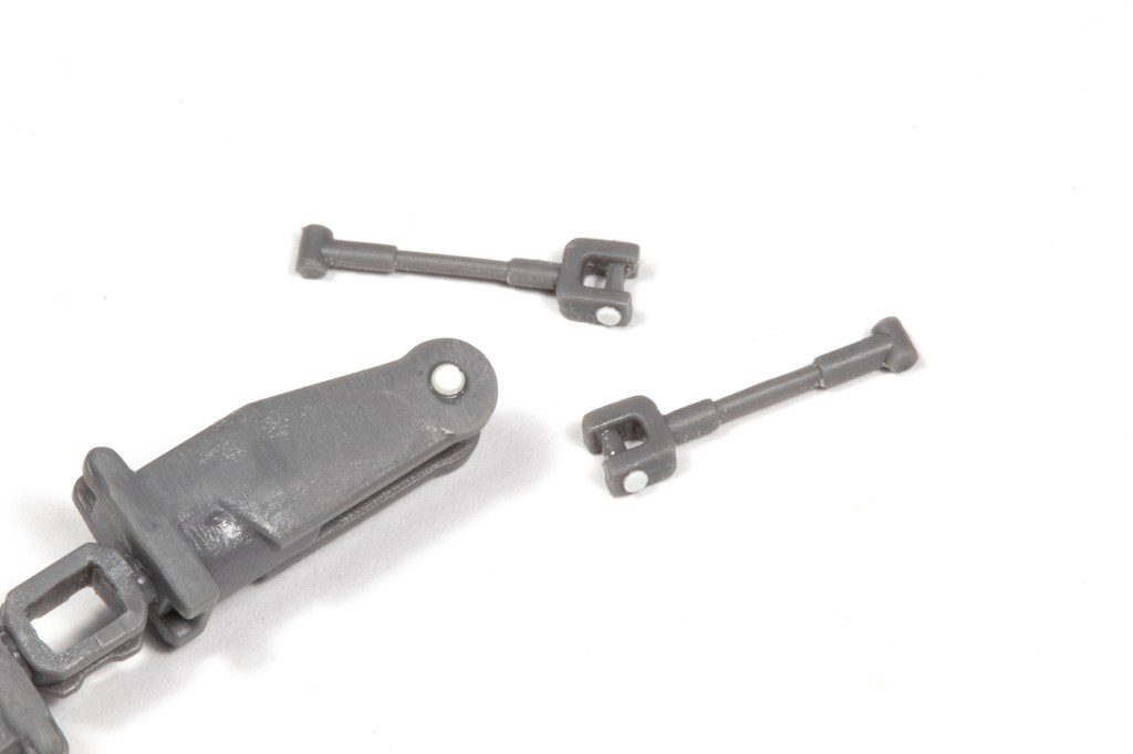
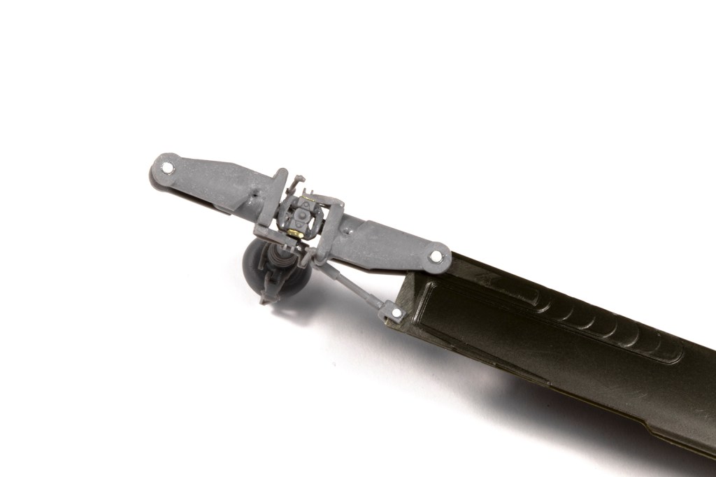
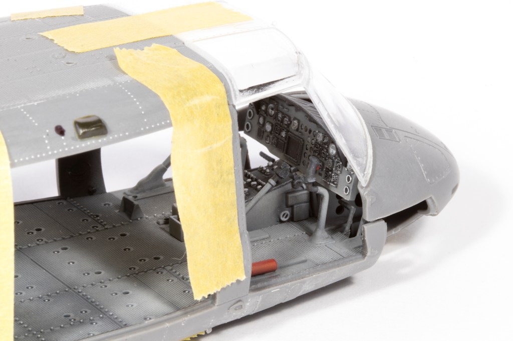
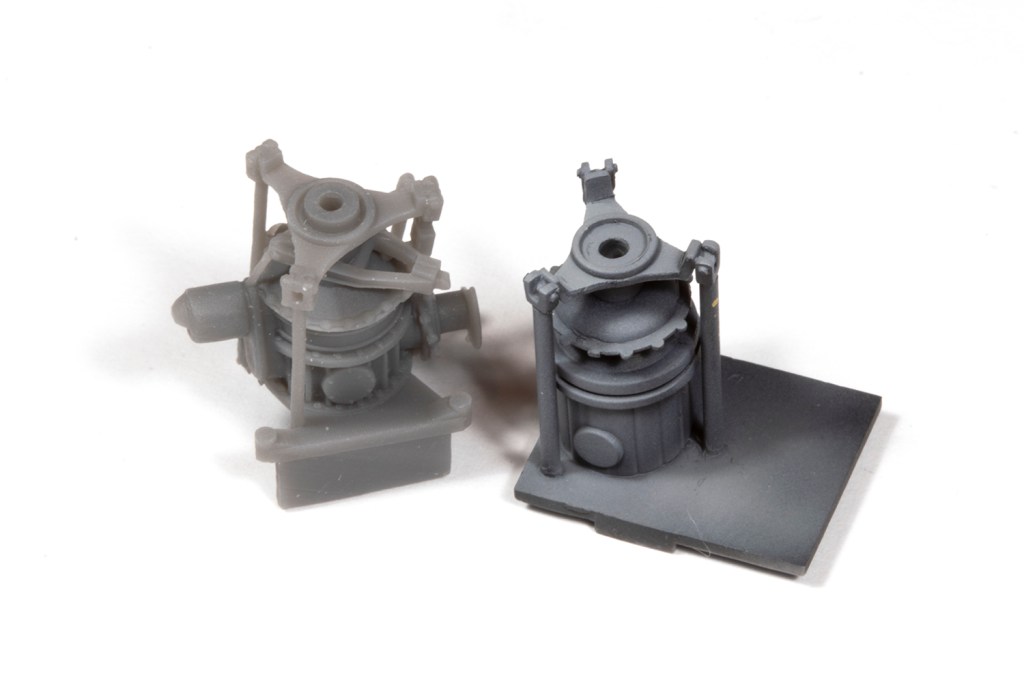
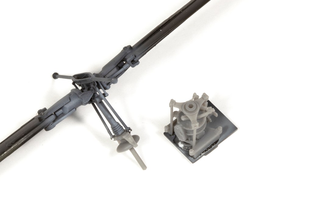
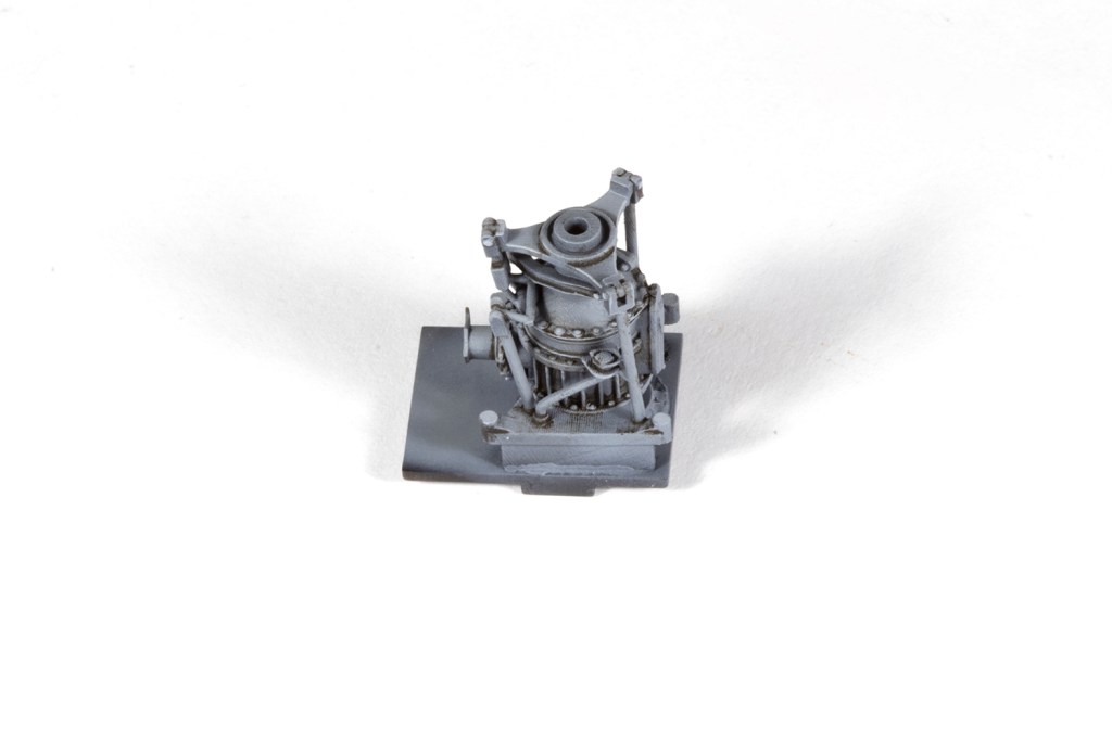
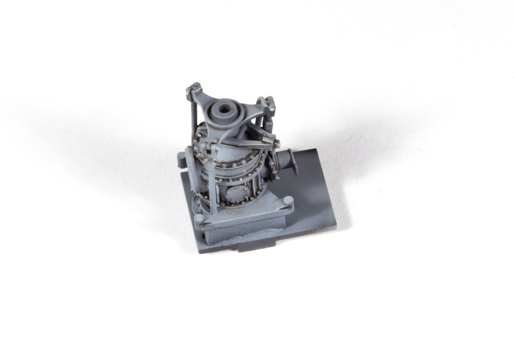
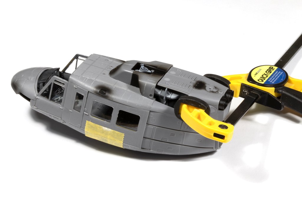
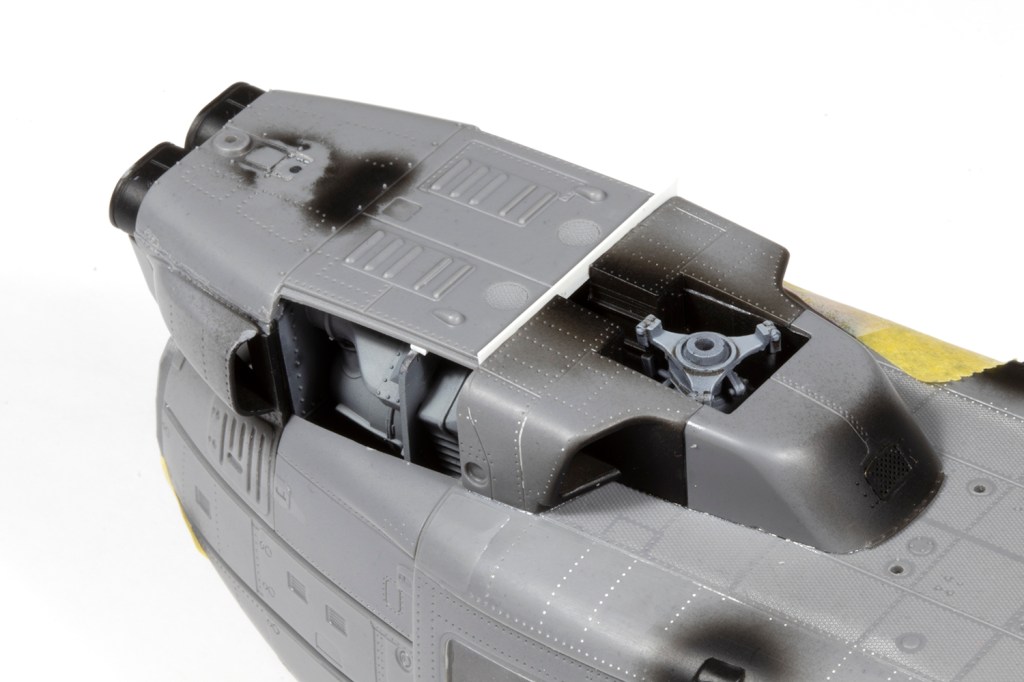
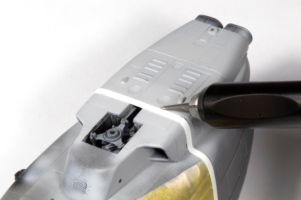
The fit of the kit ranges from fantastic (main cabin doors; windscreen) to rubbish (engine covers). I did lots of test fitting, and discovered the instrument coaming interferes with the windscreen/nose, and so I moved it aft a millimetre or two – make sure you test fit this, too, otherwise the cyclics will get in the way of the panel. The windows for the main cabin doors have a weird corner that needs to be sanded away, and you also need join the rotor transmission mount (parts C28/29) to the base (B27) prior to adding the connecting rods (C1). If you follow the instructions you will end up in a pickle. I used the Werner’s Wings 3d printed rotor transmission and adjusted it to the same height as the kit part. This was a mistake as my rotor now sits too low.
I’ll also mention that parts A34 (scissors at the base of the rotor) are the mirror image of what they should be, which means the very long and distinctive rods to the top of the rotor (parts C19) twist the wrong way. This is solved by the Werner’s Wings parts (and the ResKit equivalents, if you can find them).
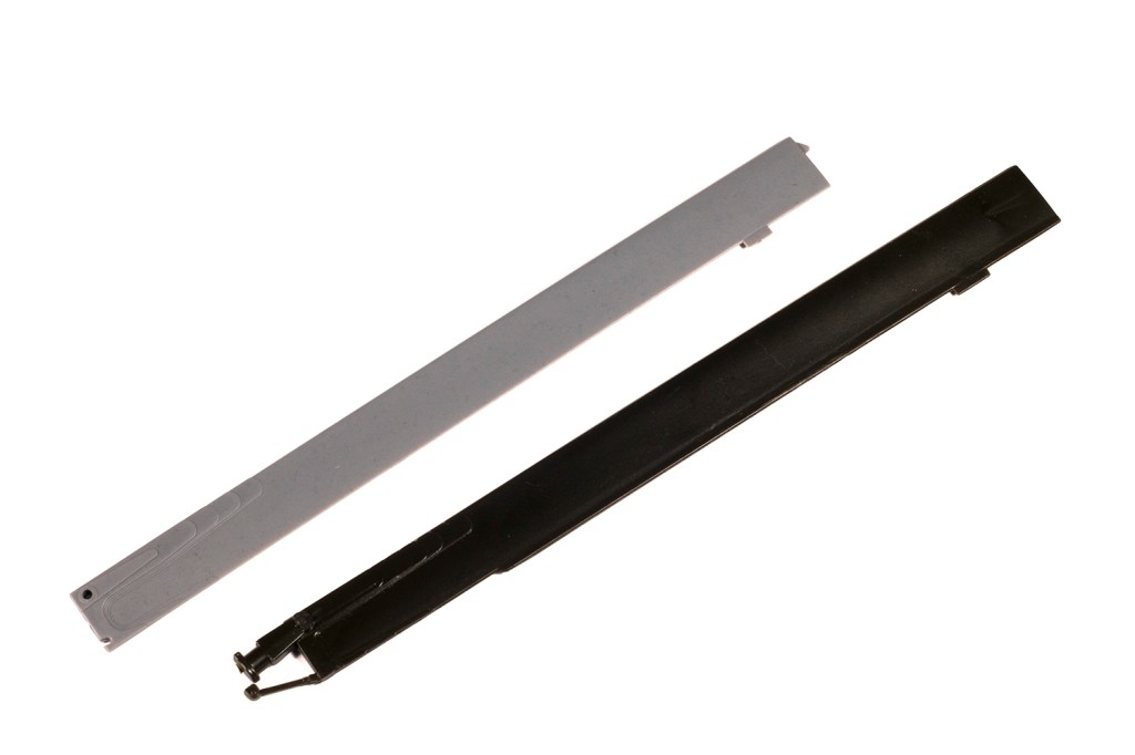
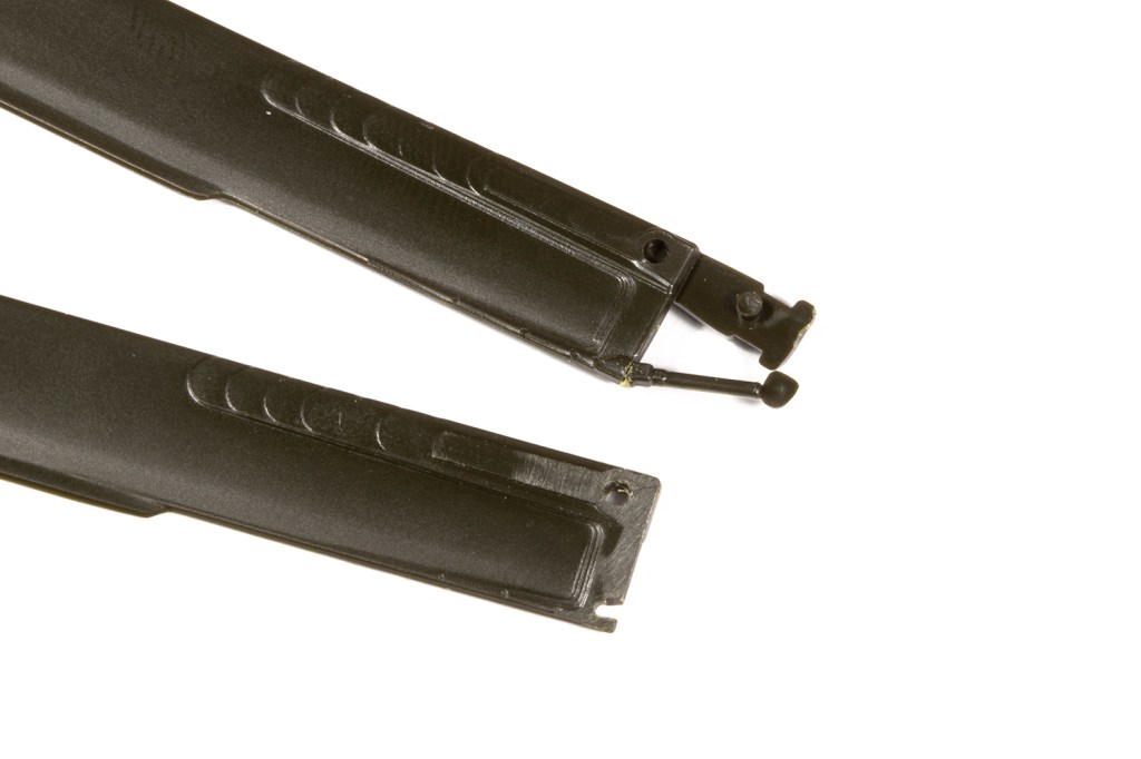
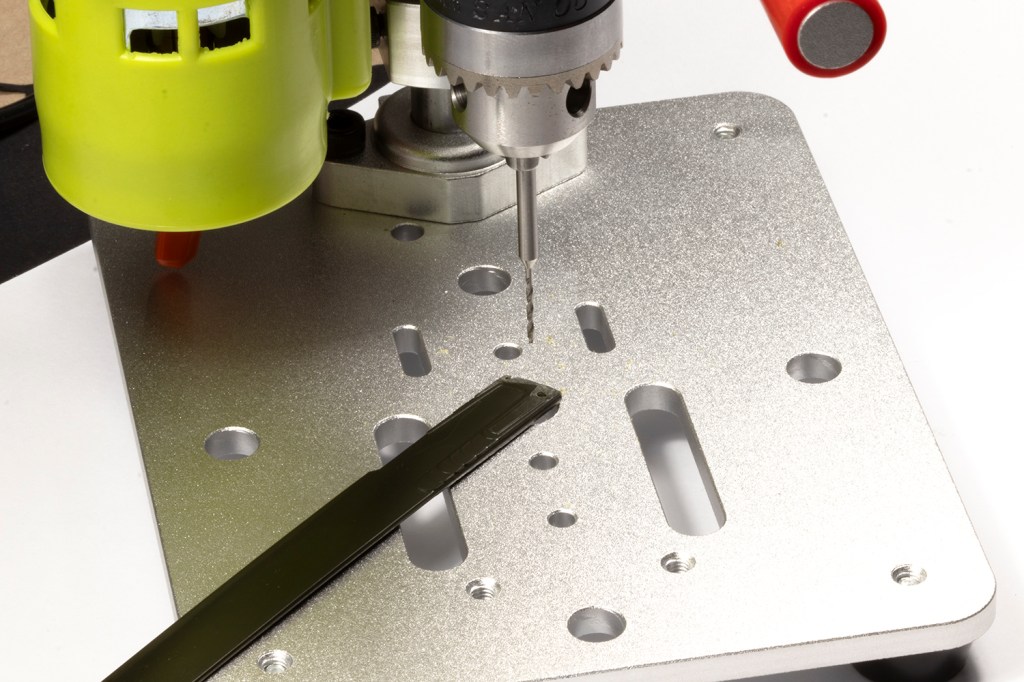
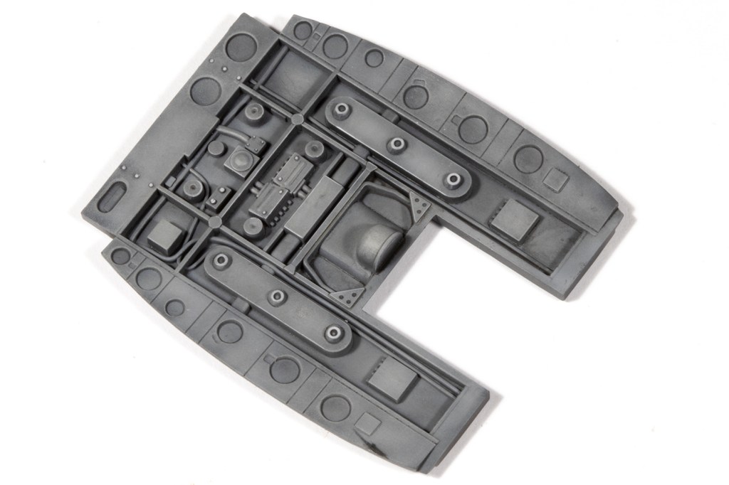
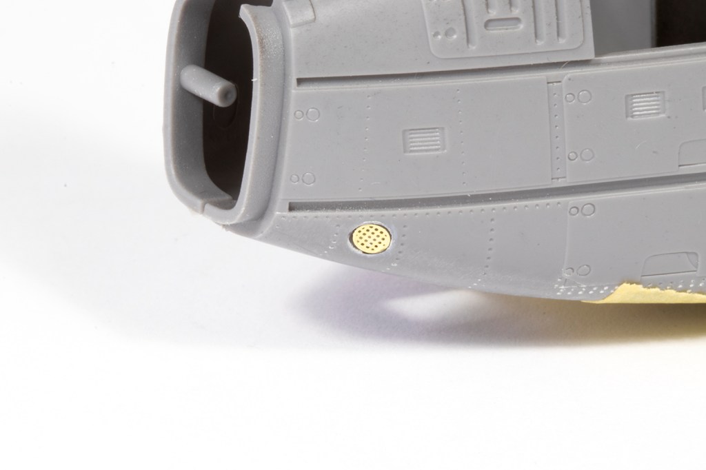
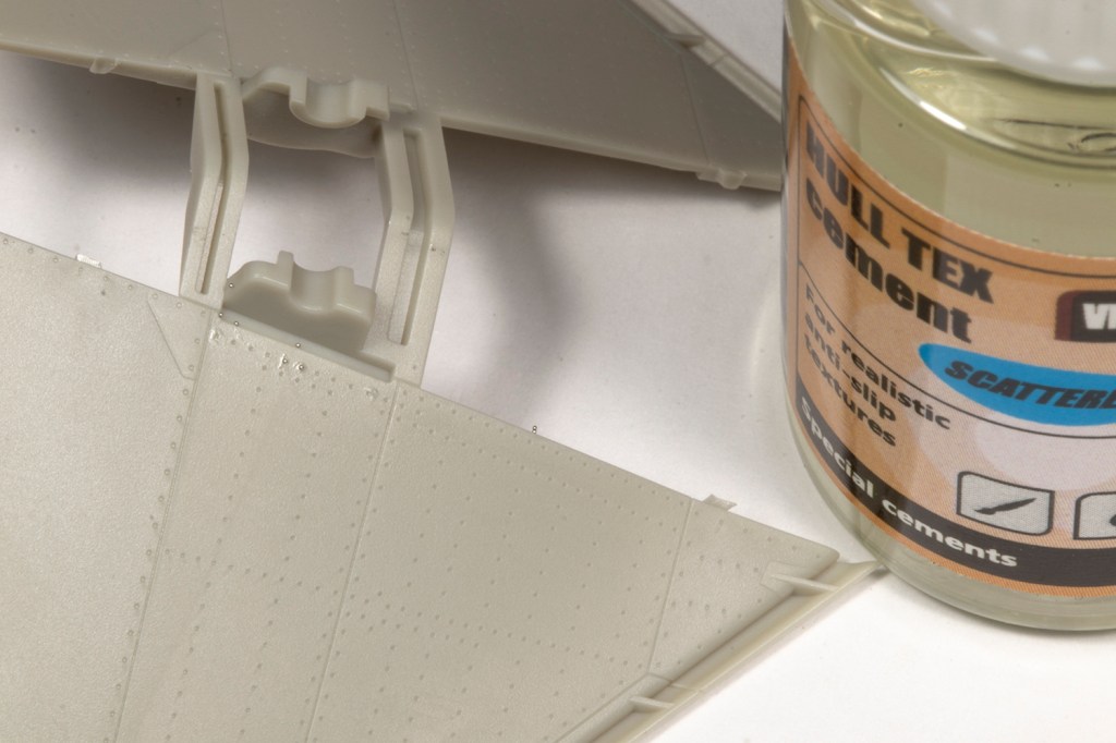
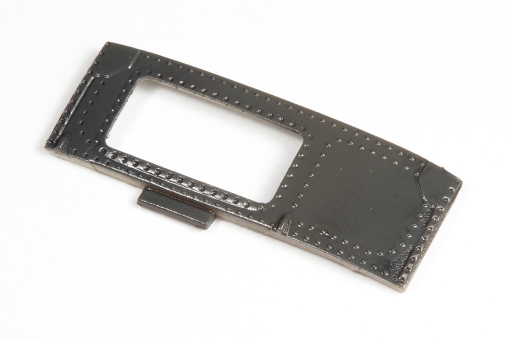
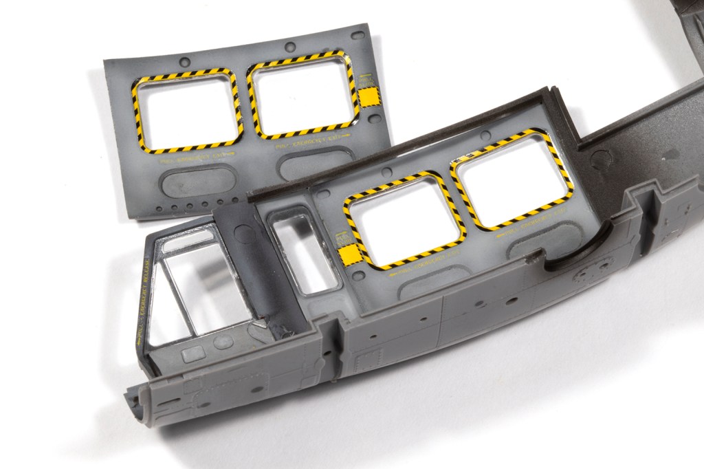
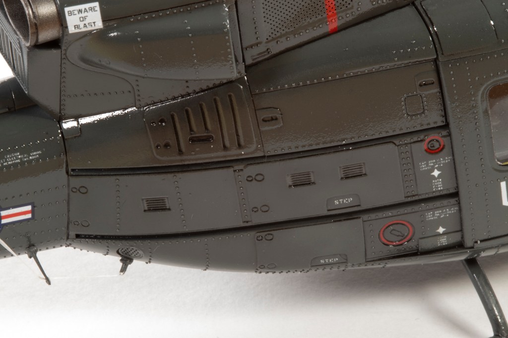
At some point I picked up a little correction set by Flying Leathernecks from Hannants, which was a set of thin plastic parts to replace the slightly inaccurate panel detail under the tail boom. I only bothered because it was cheap and easy enough to add.
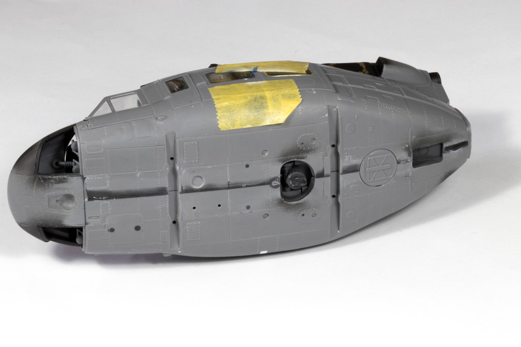
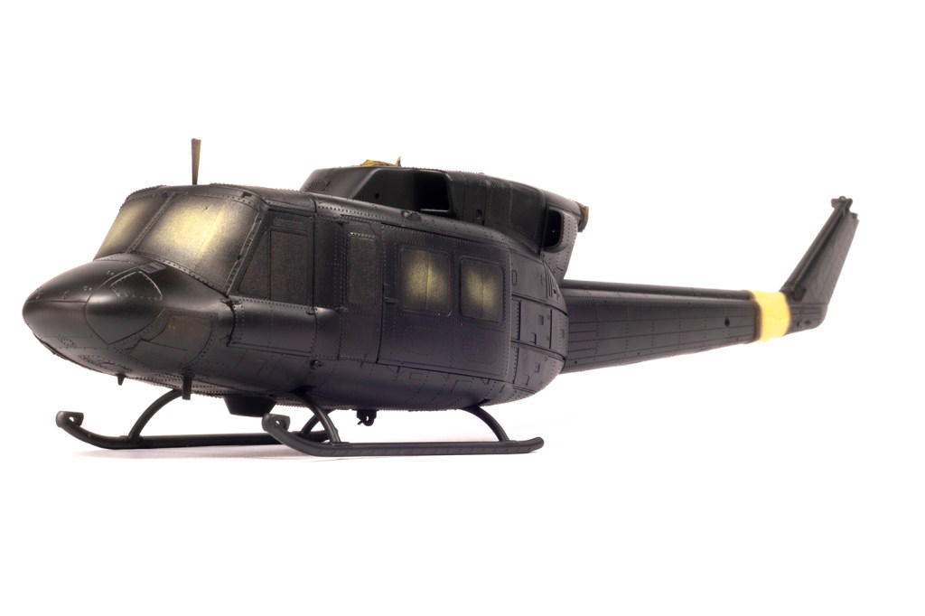
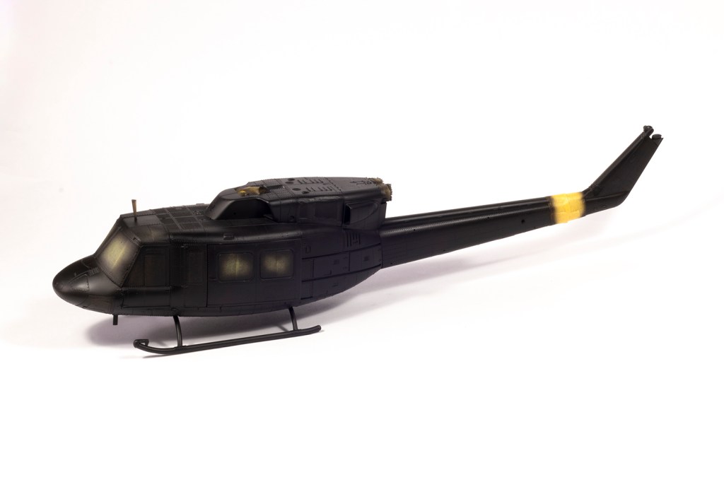
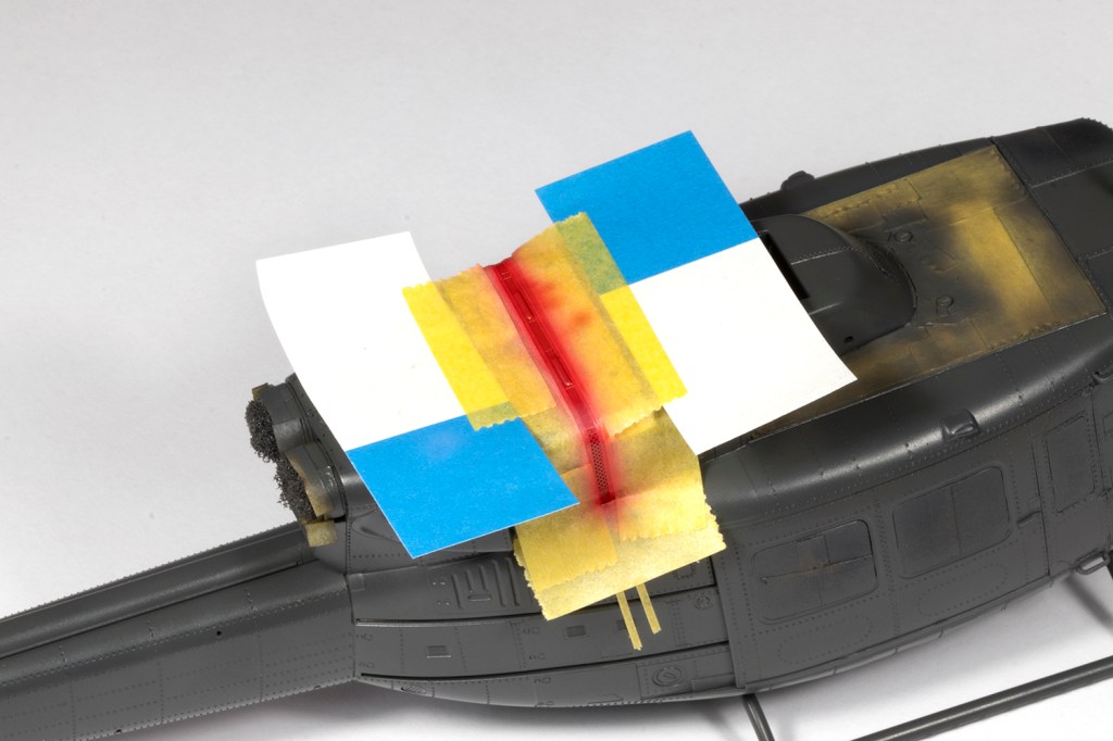
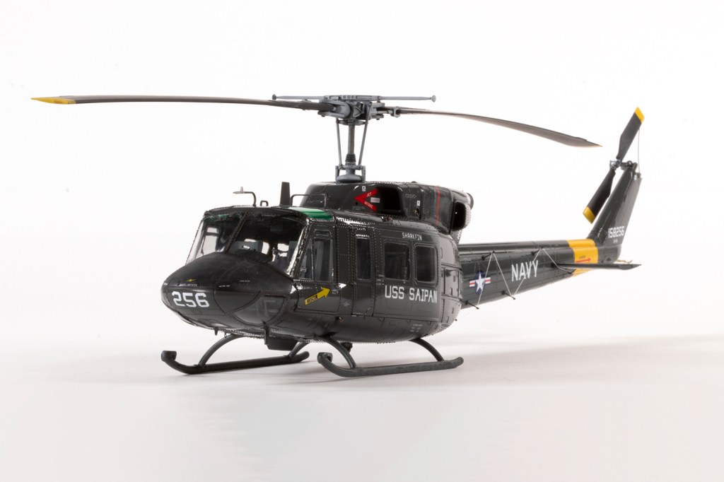
Eventually I could ignore the finish of the Twin Huey no longer, and I had to decide how I was going to make it glossy. Over a black primer layer, I airbrushed some generous coats of Mr Color 339 Engine Gray, which is quite glossy, but not enough. Decals went down over this, and were also courtesy of Werner’s Wings. They behaved beautifully over the rivets. Everything was then coated in a thick layer of VMS Matt to remove the evidence of the Klear around all the rivets. So far so good, and I masked all the areas I wanted to remain matt (mainly the nose and roof).
Now testing (yes, I actually did some!) had shown that VMS Gloss would produce a nice subdued finish over the matt, and so I hosed some of this on nice and thick with an H&S Evolution airbrush fitted with a 0.4mm needle. Sadly, testing let me down. It was horrible. So my next step was to escalate, and really hose on a very wet layer of Tamiya X-22 thinned about 40/60 with Mr Leveling Thinners through an Iwata RG-3, which is a mini spray gun. It took about 10 seconds to apply, then I covered it and left it for a couple of days.
The result is not horrendous, but neither is it ideal. There’s orange peel, and with so many layers of varnish, all definition around the rivets was lost. From a distance and under soft lighting, it looks okay, but close up and under spotlights, I’m far from happy.
In my opinion, trying to get a ‘realistic’ gloss over solder ball rivets is a circle than cannot be squared, but maybe that’s just my limitations as a modeller speaking. I’ve no regrets over the finished article, and I’m unapologetic for the way it looks. In a strange way, whilst I’m disappointed, I also kind of love it. It’s certainly different!
Year bought: 2025 (Temu)
Year built: 2026 (New Addington, Croydon)
Back to home.
