with ResKit resin main rotor hub, tail rotor, refuelling probe, air intakes and exhausts, Eduard photo-etched interior, exterior and cargo seat belts, Armory resin wheels and AOA decals
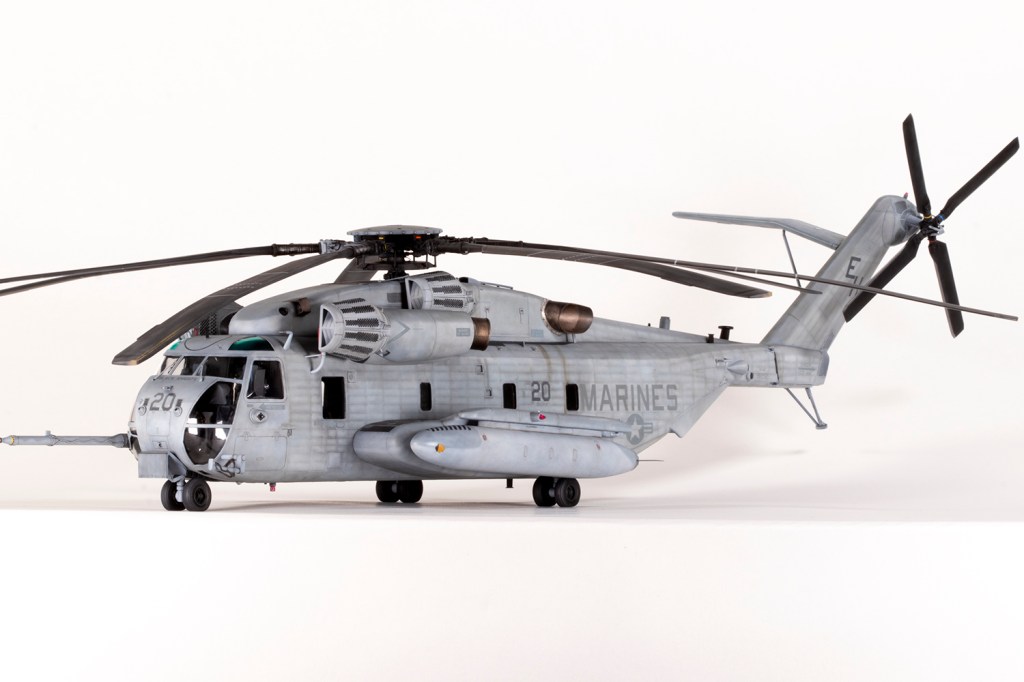
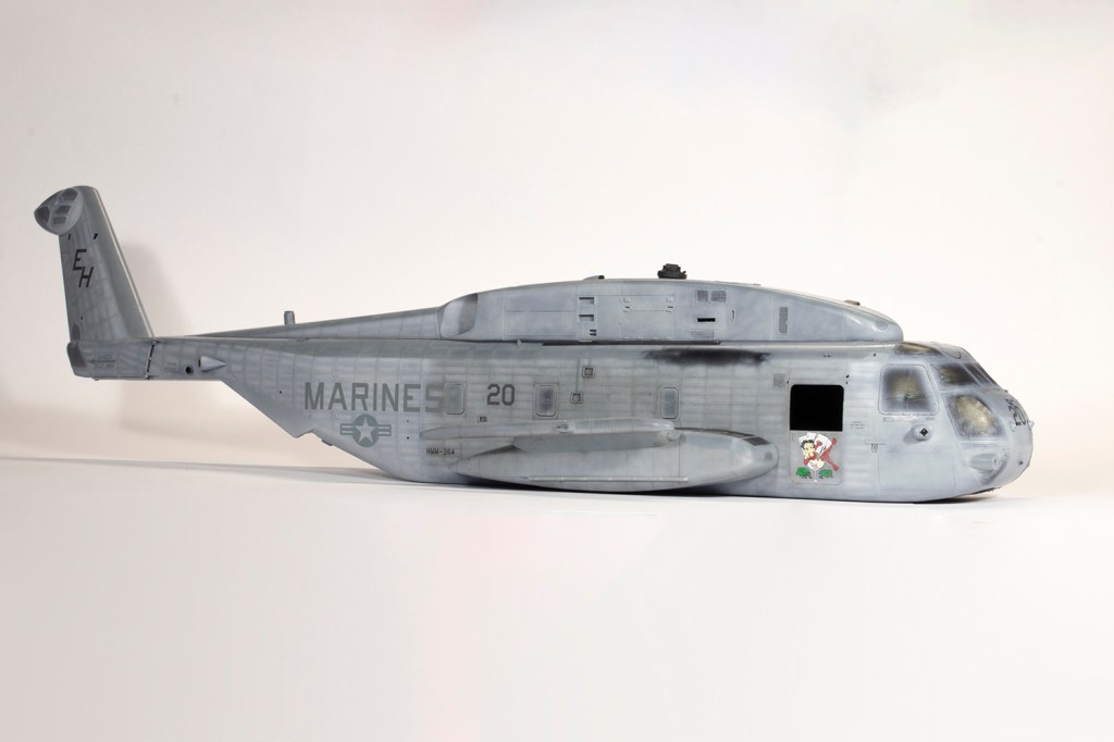
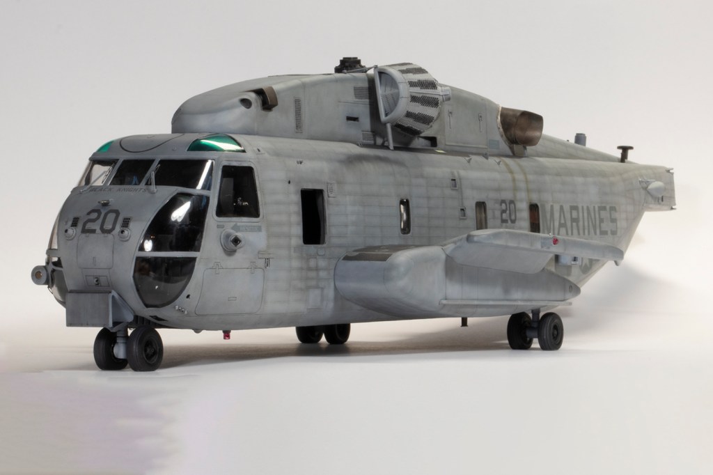
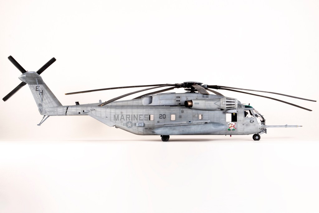
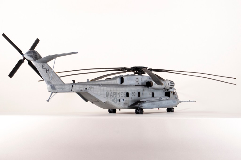
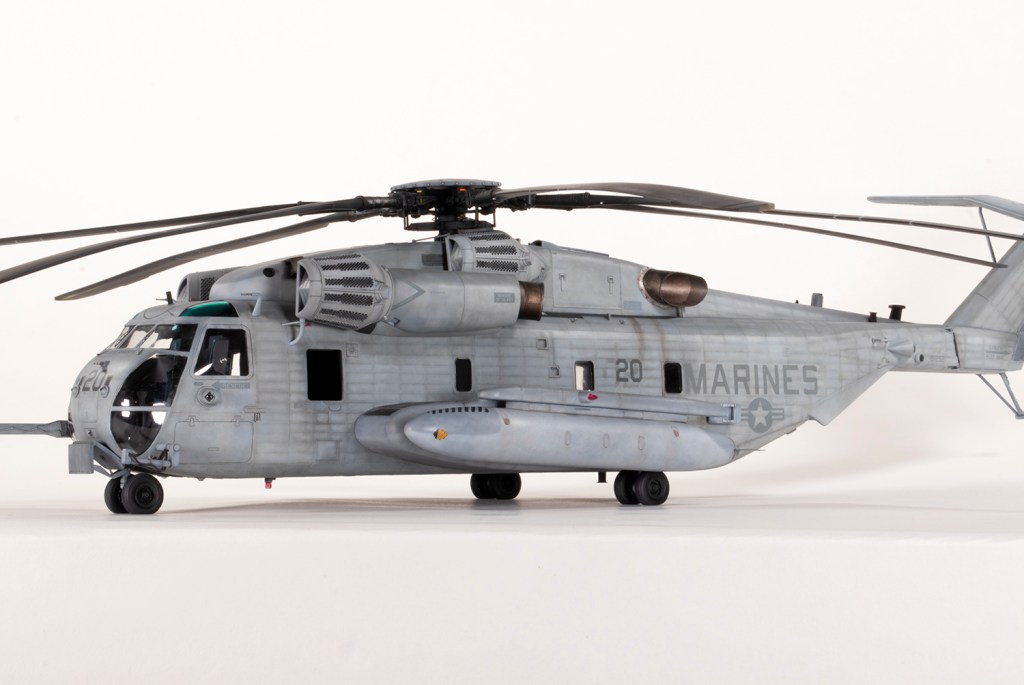
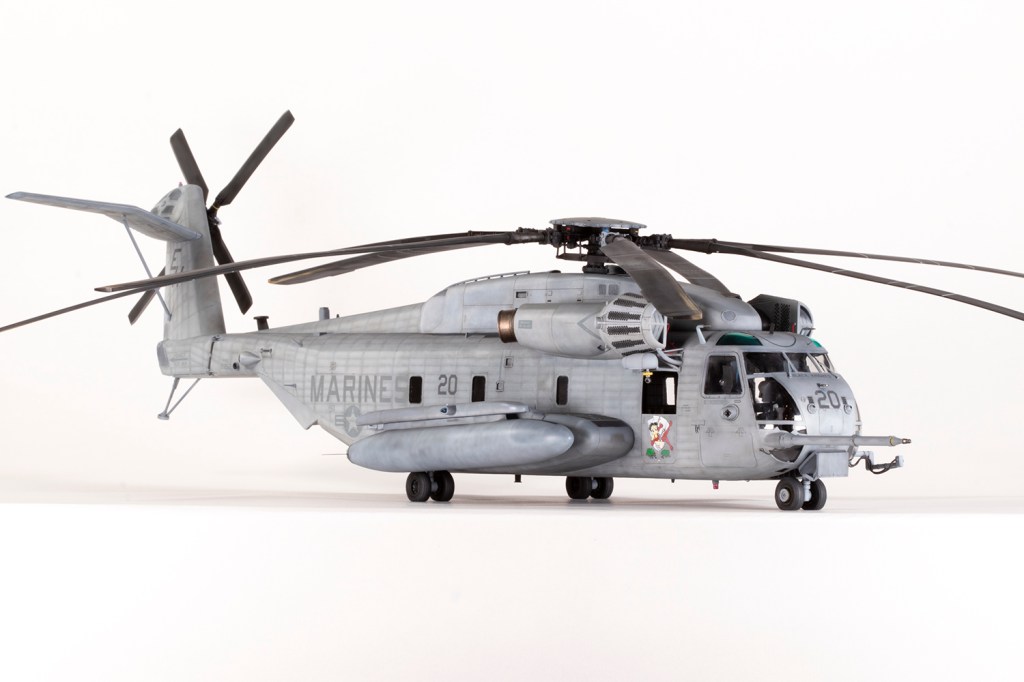
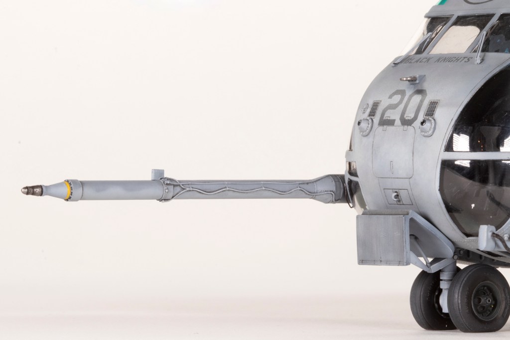
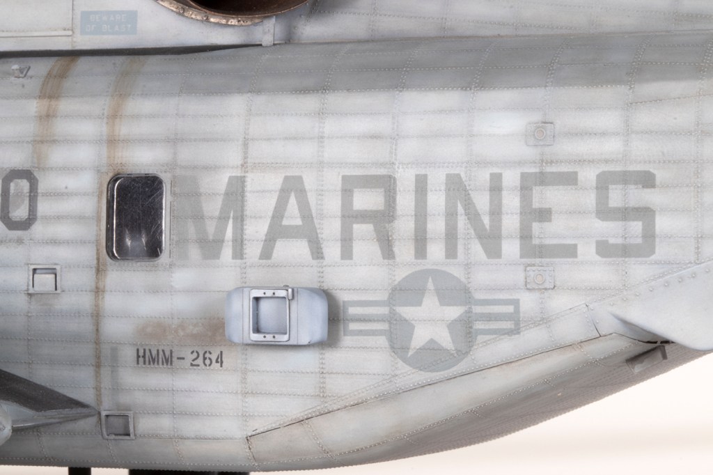
HMM-264 ‘Black Knights’, US Marines Corps, USS Bataan 2006
From 2006-2013 I lived in a backwater city in central China. When I moved there I thought I’d have to give modelling up, but it turned out I needed something to do in the evenings, and through a combination of stuff being shipped from home and mail order from Japan, I got my hobby back up and running. It was after nearly a year that I finally located a model shop some distance from where I lived, and which proved so difficult to find that in the end a phone call to the owner brought him out to pick me up! With service like that I felt obligated to buy something from his shop, and despite costing 15% of my monthly income, that purchase was this kit: Academy’s 1/48 CH-53E. It was still cheaper than buying one in the UK…
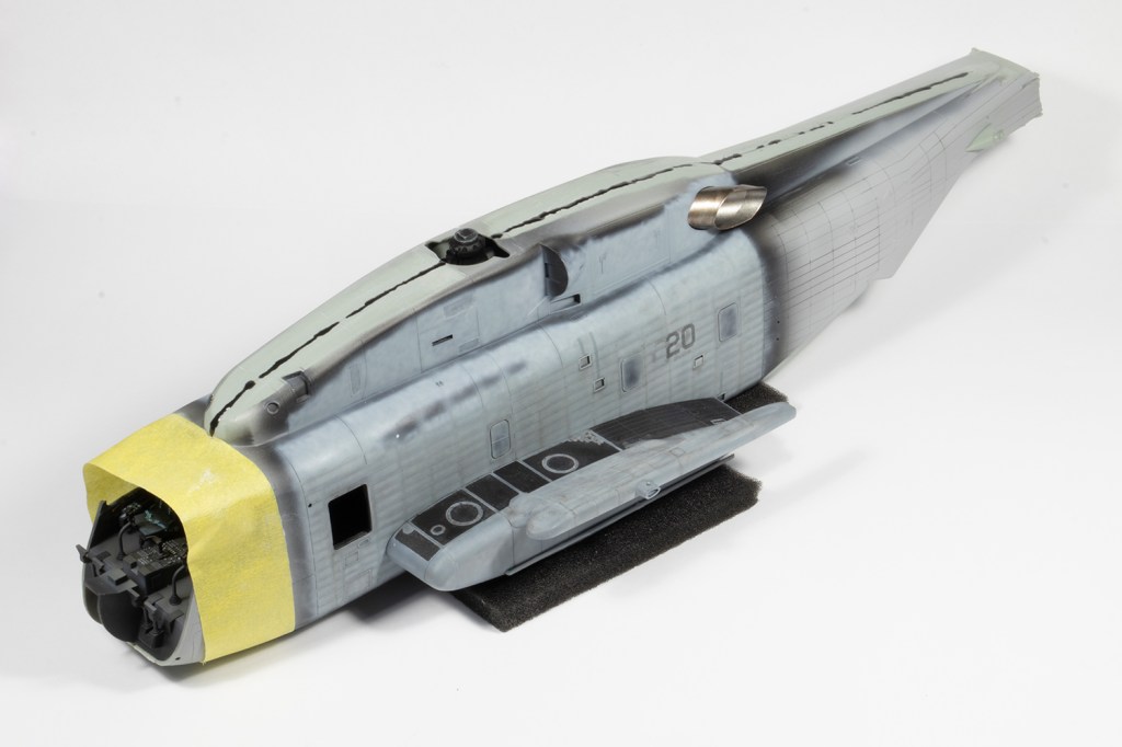
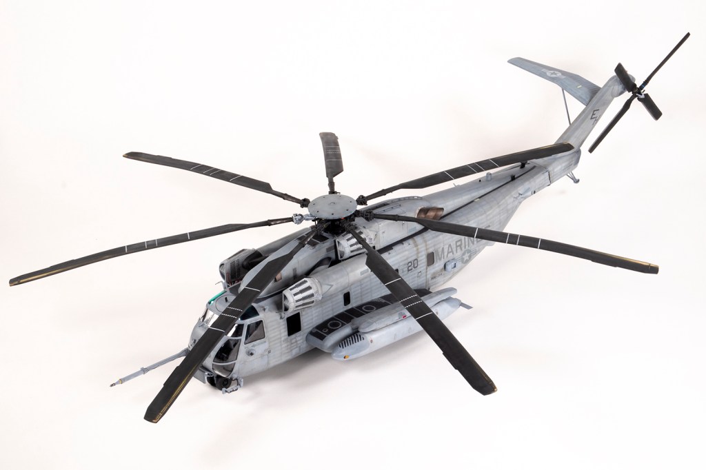
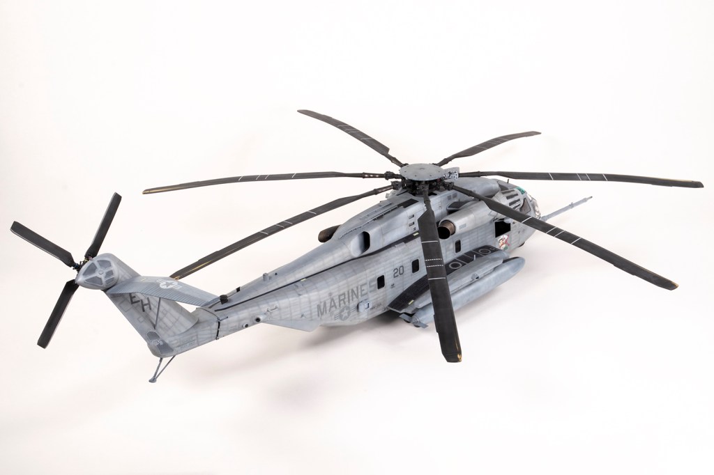
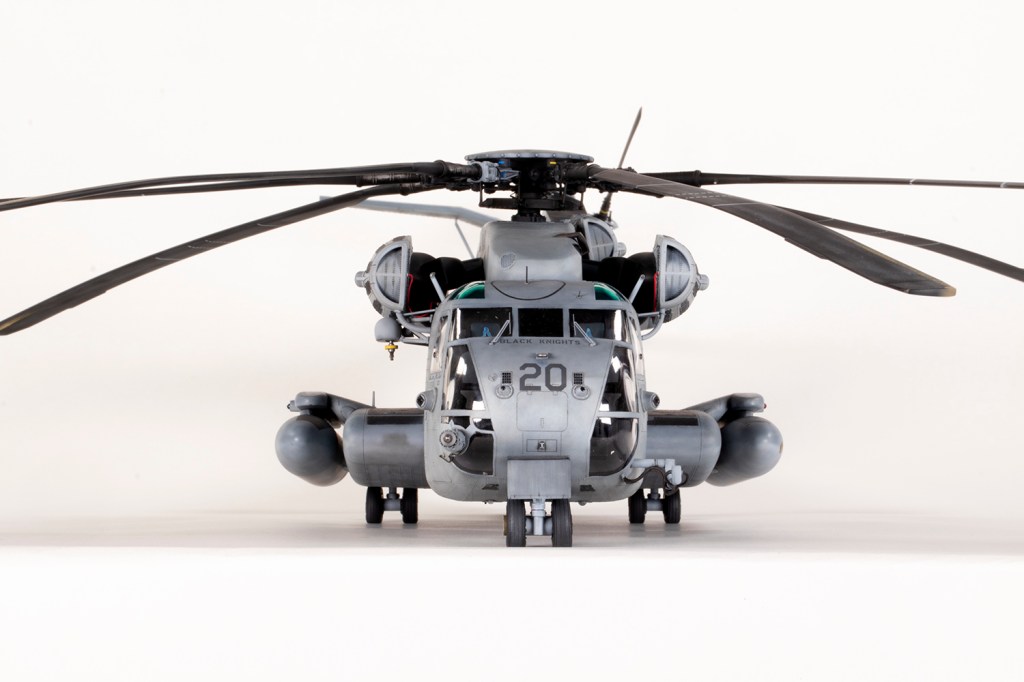
It was in 1981 with the addition of an ‘E’ that the CH-53 Stallion became ‘Super’ and gained an extra engine, rotor blade and canted tail (amongst other things). It’s a massive beast, significantly longer than the CH-46 I made in 2022 and with a rotor diameter of 50cm in 1/48 it has a footprint bigger than a Catalina. I was always going to make mine with everything extended, which will condemn it to a very dusty existence on top of a display cabinet rather than in one.
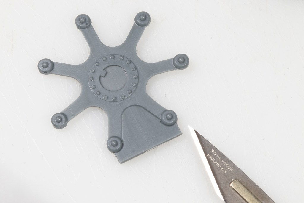
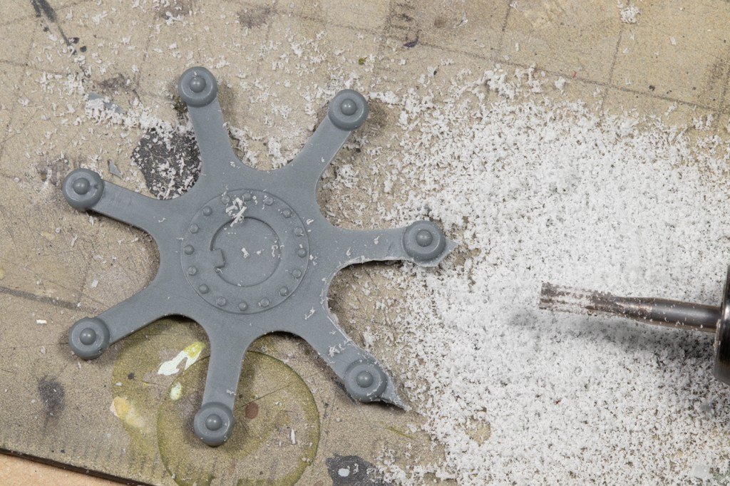
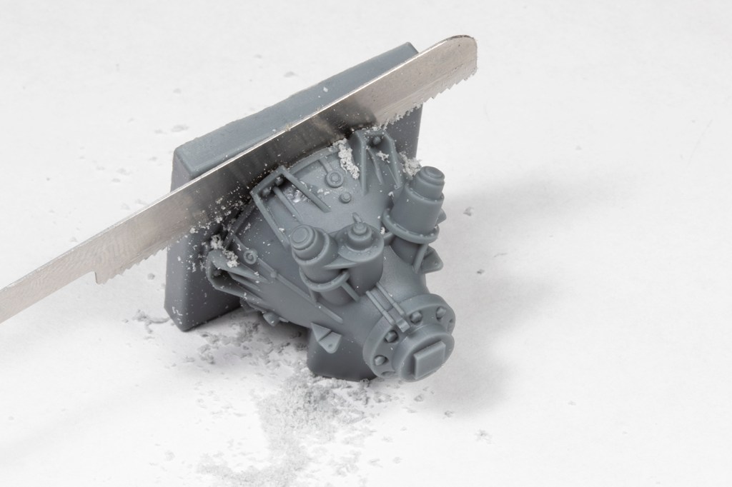
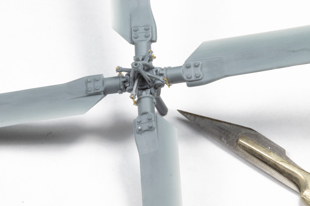
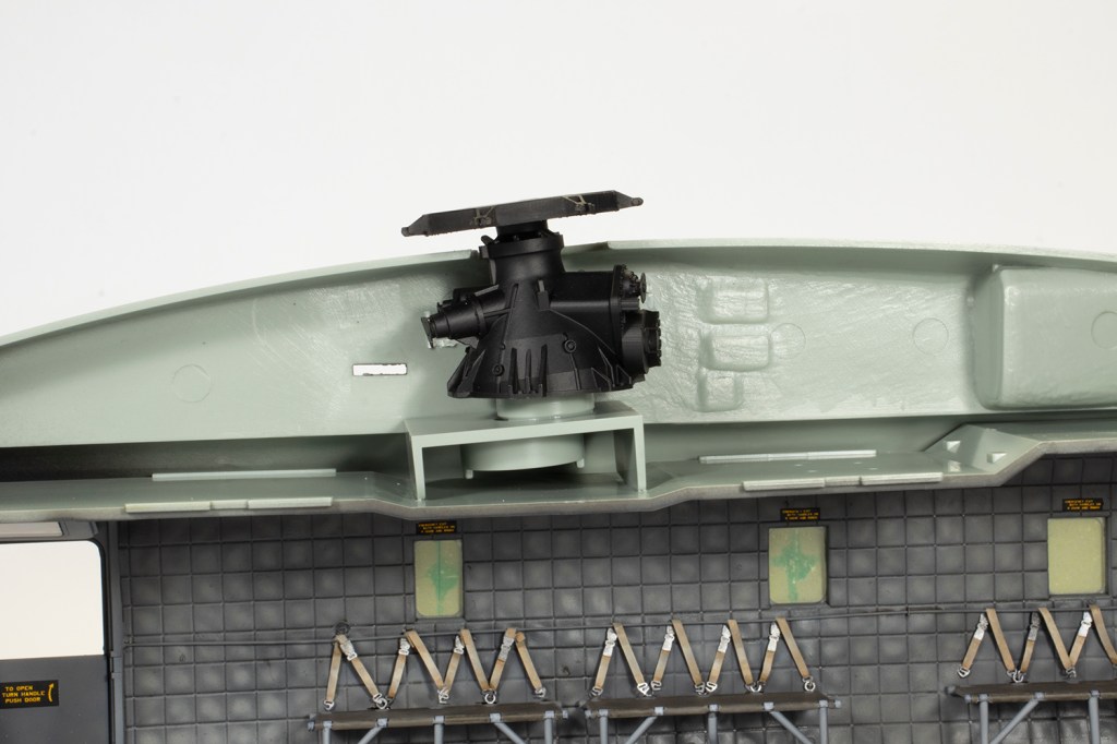
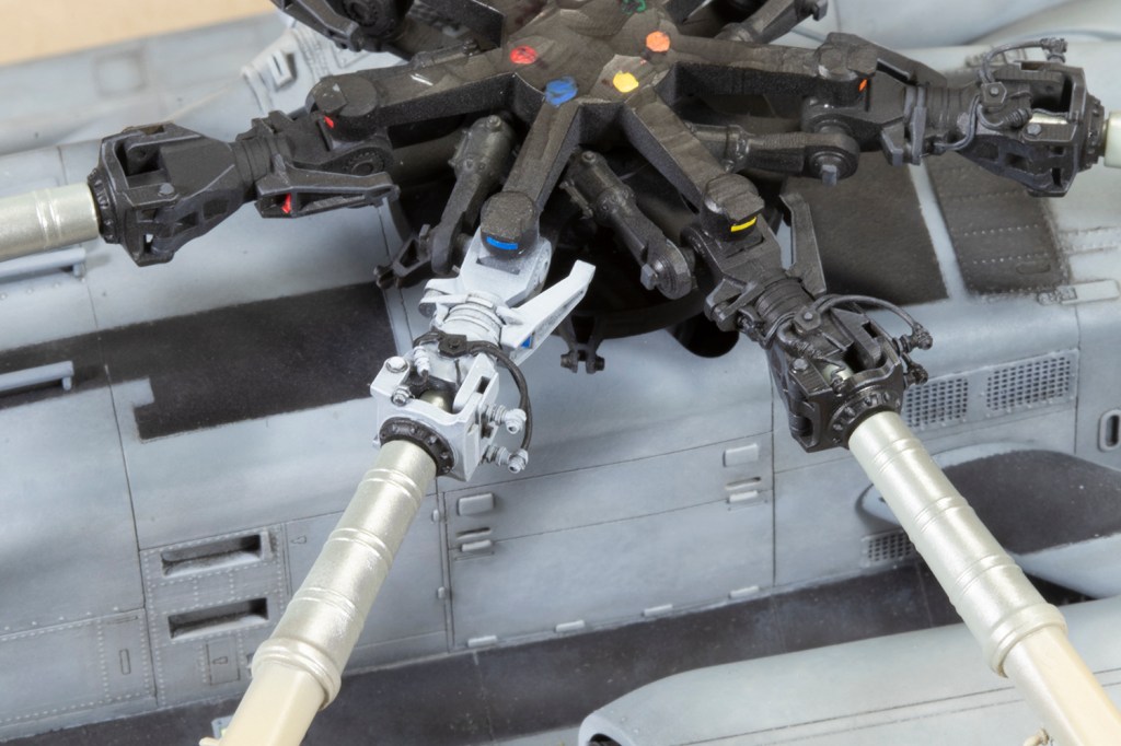
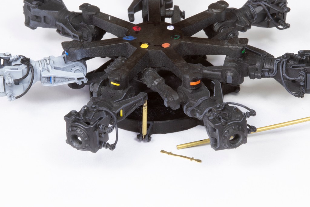
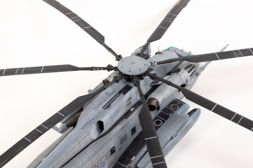
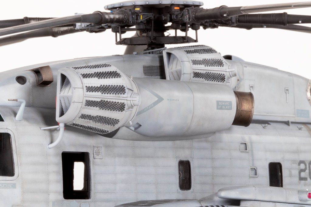
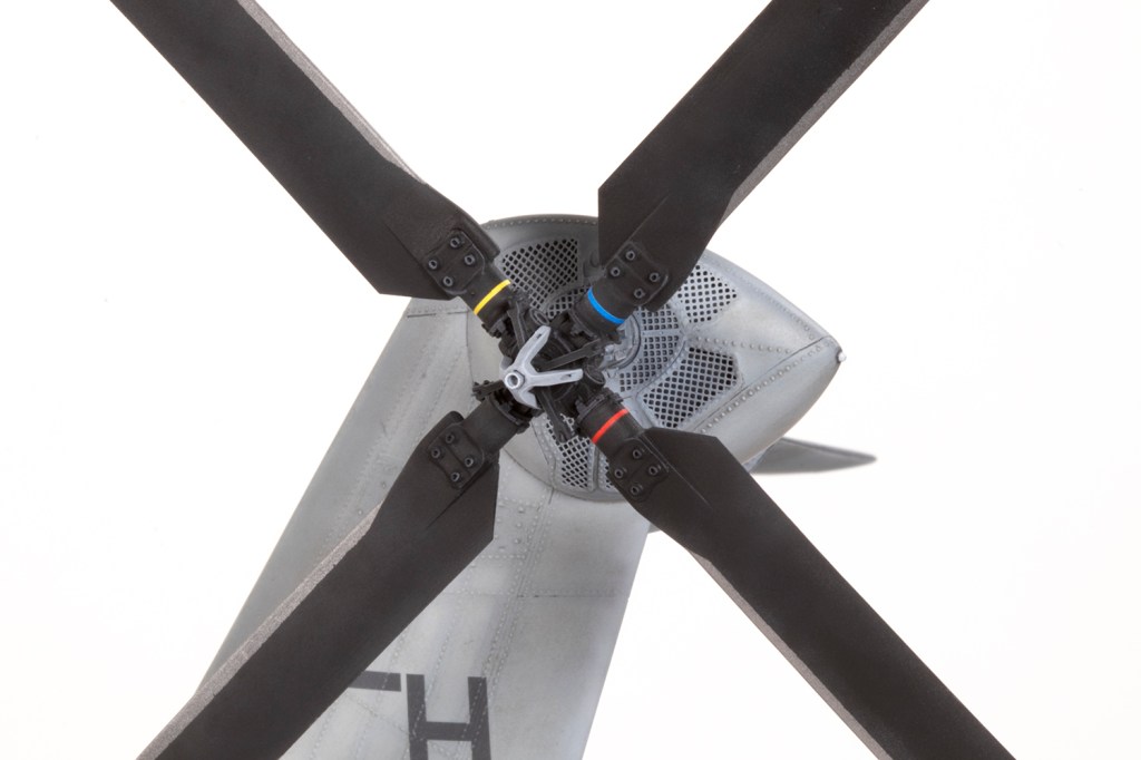
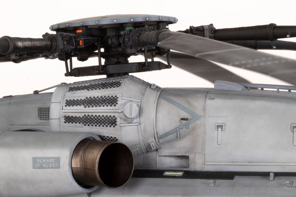
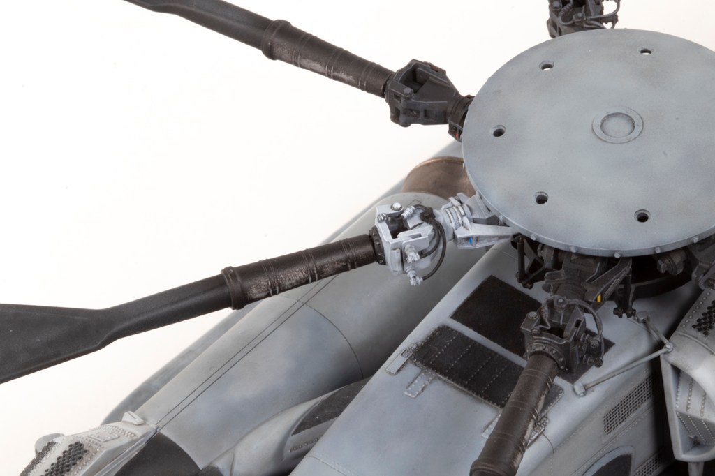
Because I was waiting on some PE to arrive, I ended up building this helicopter inside-out (or outside-in), and didn’t touch the interior for well over a month. Work focused initially on the rotor head, which is a fairly complex assembly from ResKit. However, close examination of my references (I was using the excellent and recent publication from CAVU Publications) showed the ResKit detail set was not nearly complex enough. In fact, the detail upgrade offered by the resin set is minimal at best. As you will see, I turned out not to be a great fan of this set…
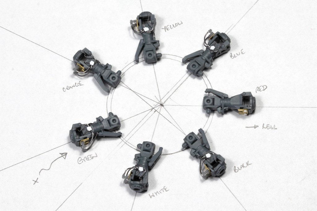
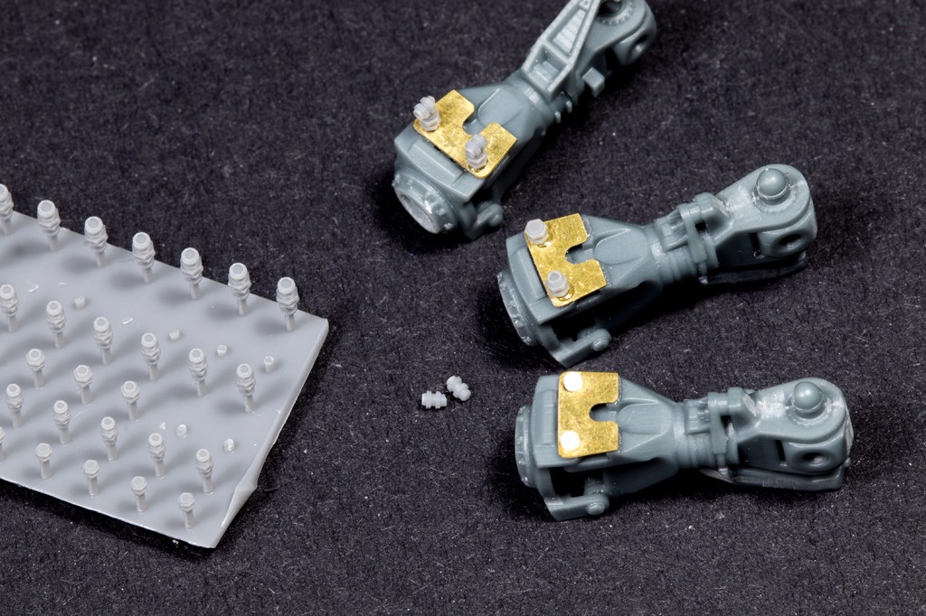
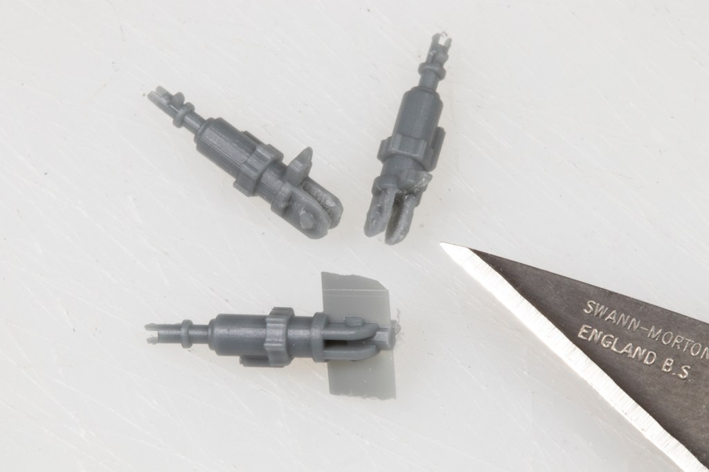
The first issue is a left/right confusion. This is going to get very detailed and you may want to skip it, but if you’re actually going to make a Super Stallion it’s rather important. There are seven rotor blades, six of which fold. The non-folding blade aligns to the tail and three fold rear from the left, and likewise from the right. This means the hinges for the fold are mirrored. I made the critical mistake of following ResKit’s instructions and they are wrong. They would have you make four for the right side (step 1 of the instructions) and three for the left (step 3), because the non-folding blade still has a folding hinge, it just doesn’t actually move. In fact, you need three for the right and four for the left. Step 4 of the instructions illustrates the error because you can see two opposing hinges labelled as the same part (i.e. they should be different). In short, the diagram (but not labelling) in step 4 is correct so start with that and work backwards. The situation is not helped by ResKit mixing up the Left and Right labels between the arms and the hinges – you need to join ‘Left’ to ‘Right’ and vice versa. Although I realised all this after making the arms up, ResKit actually supply an extra, so I was able to recover. If you’re using the kit parts, it’s worth noting that Academy also got it wrong – part G9 (the non-folding hinge) is moulded as a mirror image of what it should be.

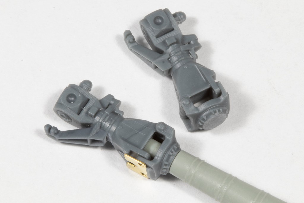
Problems continue with ResKit making no accommodation at all for the set to be user-friendly. The prime example of this is that the rotors are meant to just butt-join to the rotor arms. There’s no way this will hold, so 3mm holes need to be drilled into the end of each hinge plate and through to the arm, and the locating pegs on the rotor blades trimmed to match. This is inaccurate, because the locating pegs go right through the hinge, but it replicates what the kit parts do, presumably because there’s no other way to cope with the weight of the blade at the join.
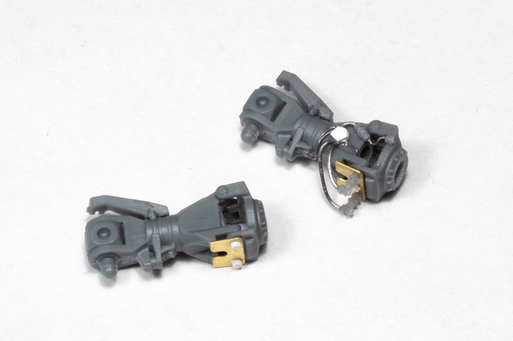
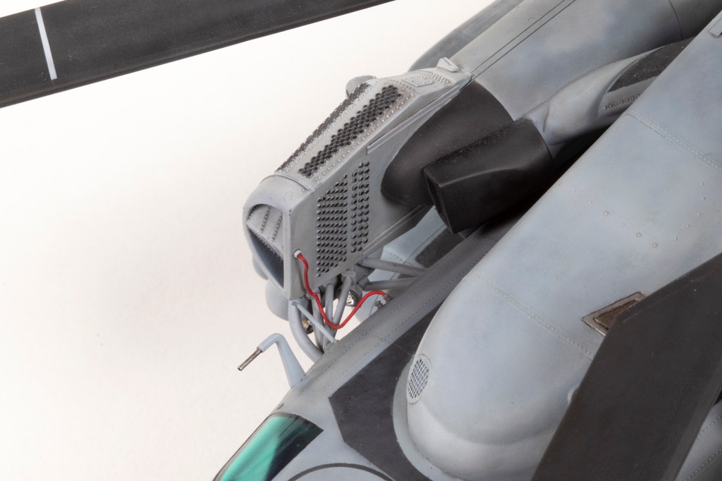
The ResKit rotor arms are hugely simplified and make no attempt to reproduce any of the extensive wiring or hydraulic folding apparatus. Although I hate detailing with wire, I couldn’t leave the arms alone and embarked on adding lead wire here and there to at least give the appearance of it being more complicated. I used some ANYZ resin line connectors to imitate the general morphology of the area (which even Academy managed) but note that the non-folding blade has none of this detail.

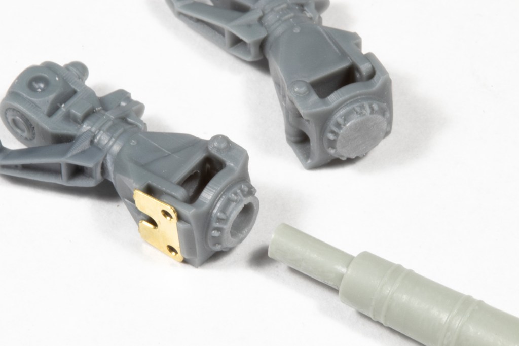
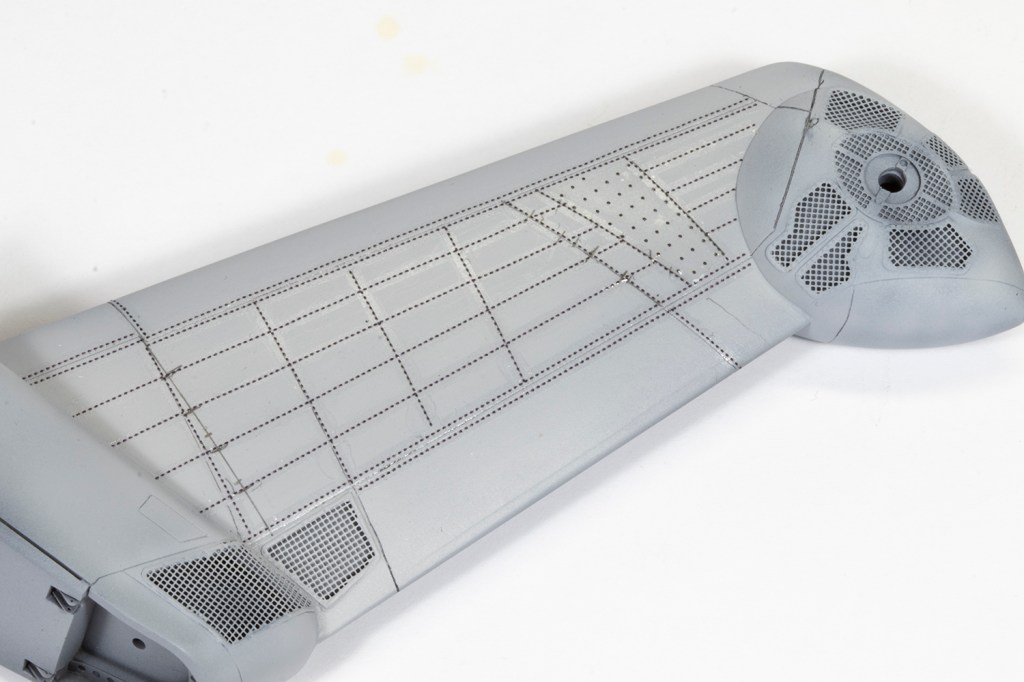
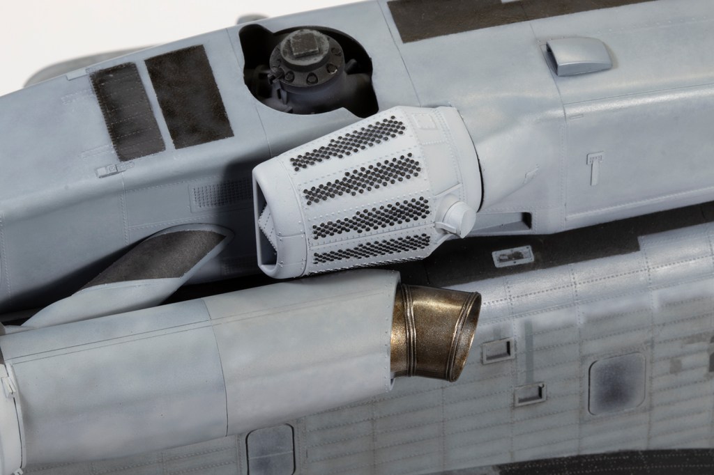
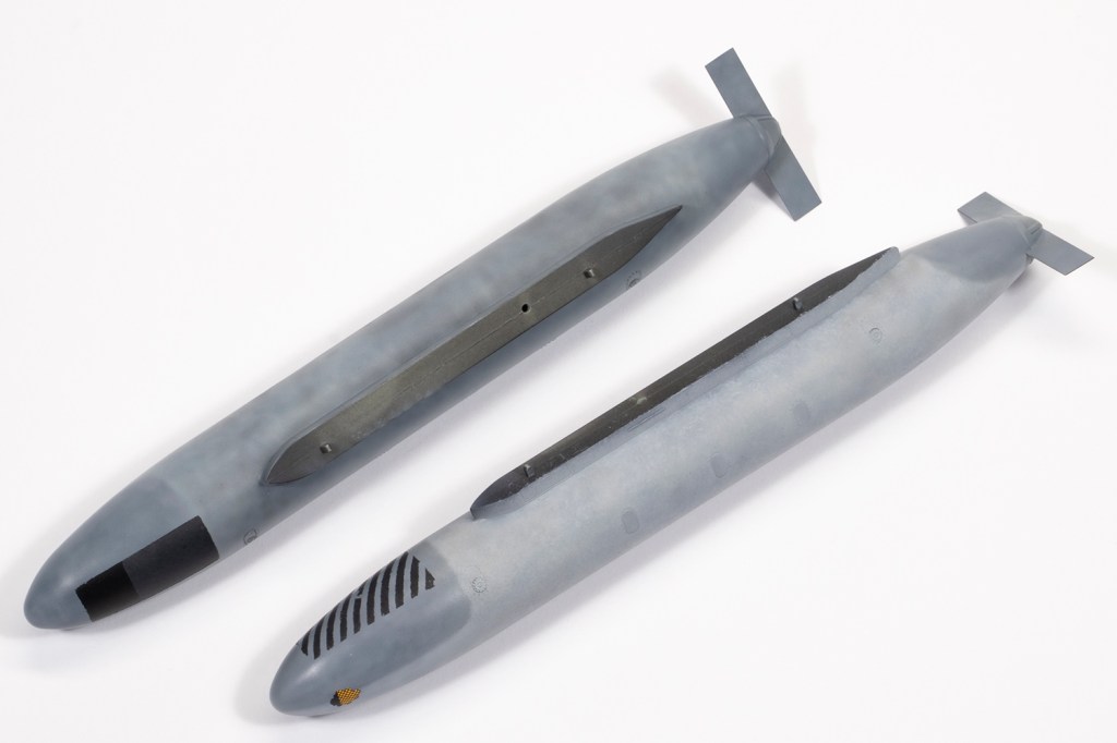
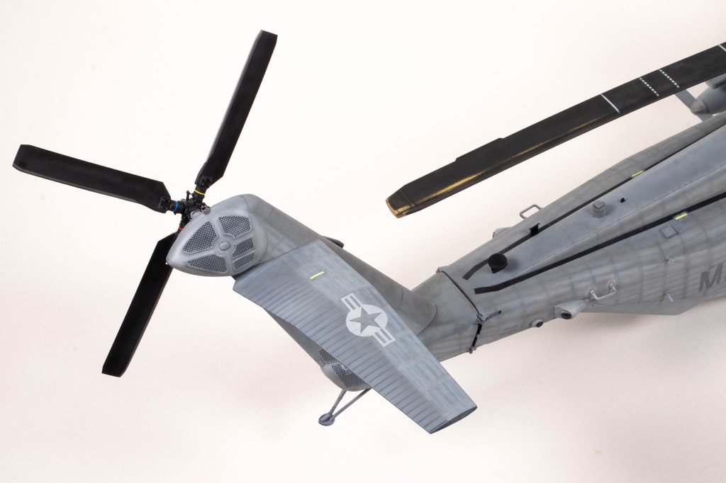
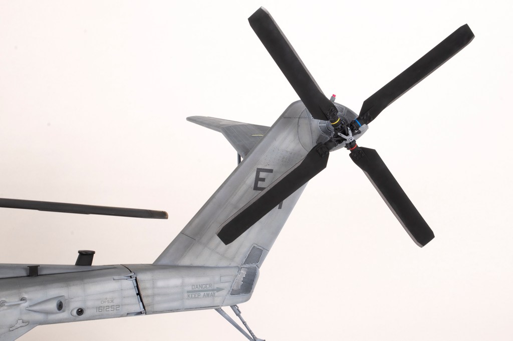
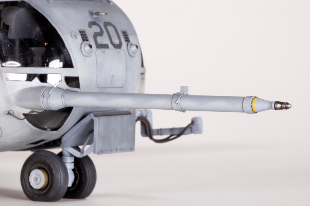
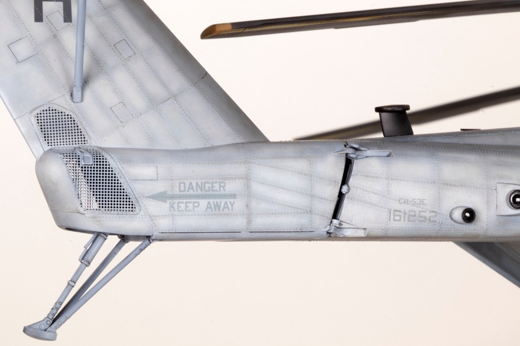
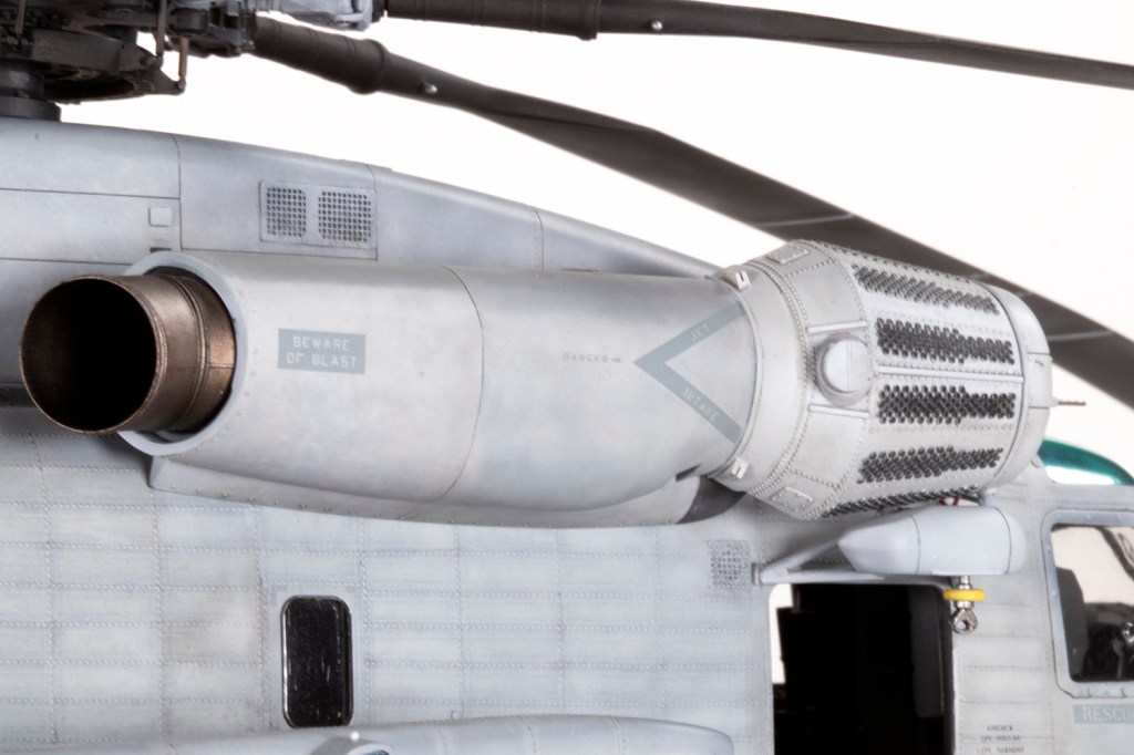
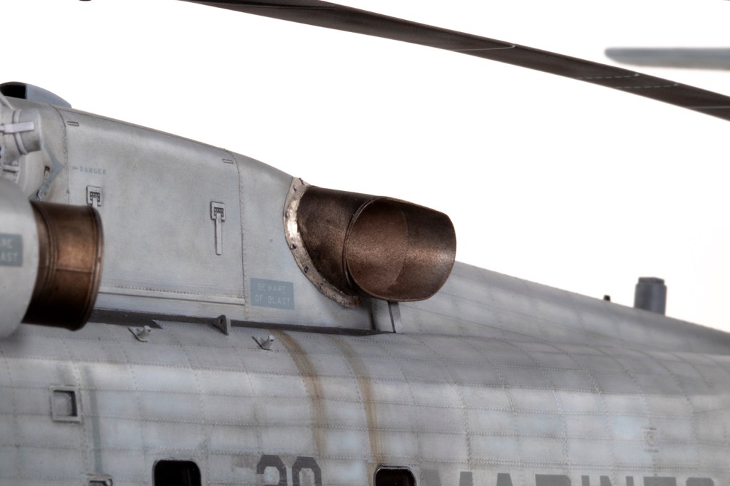
It wasn’t a terribly auspicious start for the ResKit upgrades, and I had purchased more. The tail rotor is fine, if a little soft in detail and two-dimensional, but it’s an easy and worthwhile change. The resin refuelling probe is simple but very bendy; it straightened out nicely simply by dunking it in really hot water. There’s a set of three resin exhausts as well, which are nice although ResKit could have done us a massive favour by engineering them to be installed after the engine pods and fuselage halves are joined. They do make painting difficult. Finally, I had the intake set. About which I have a lot to say anon…

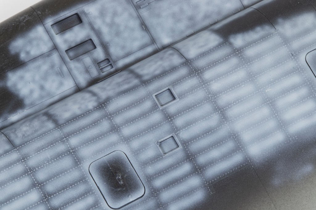
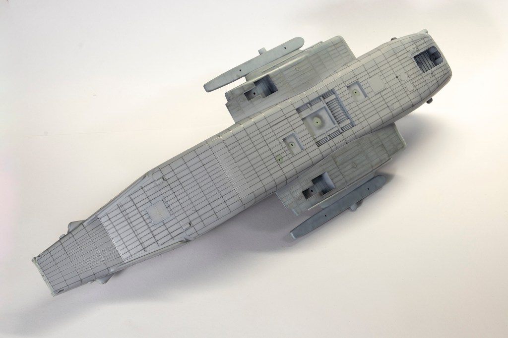
I anticipated this project would be big, not just because of all the aftermarket, but because I wanted to rivet the airframe. With positive rivets. And that takes ages. Very close examination of the kit plastic shows that Academy must have considered moulding these rivets as very faint lines where they go are visible. It’s a shame they didn’t follow through as in my opinion they’re a defining feature of the real thing. As with my Sea Knight, my strategy would be to use resin rivet decals.
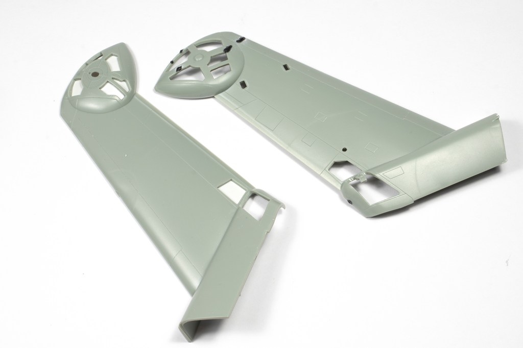
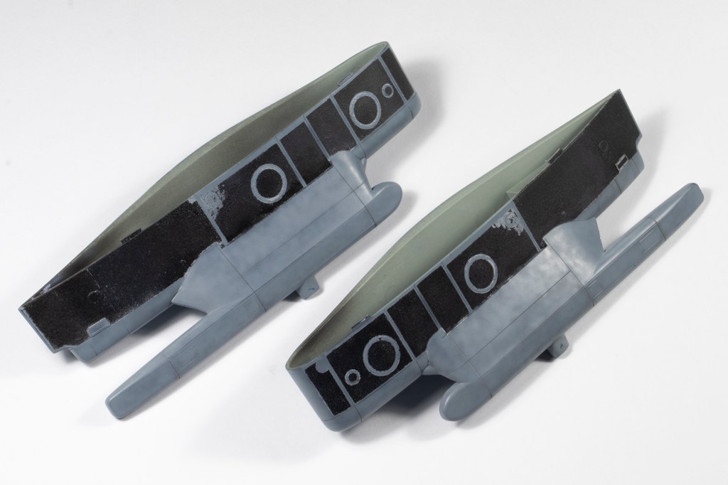
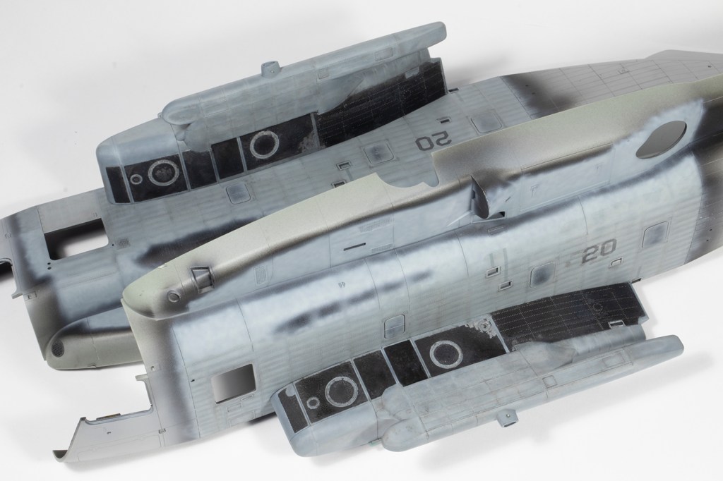
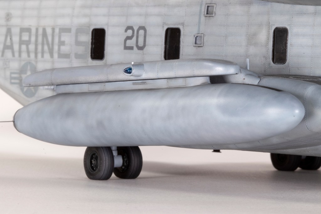
It was here I really had to think this project through. The large side sponsons fitted well to the fuselage sides, but needed pressure, and I didn’t want to risk this with the fuselage halves together lest I start splitting seams. The other consideration was the perpendicular angle between the sponsons and the fuselage sides which would be a dead cert for dusty paint. I couldn’t sand out dusty paint because I was using resin rivets, which can be fragile. It’s all very complicated, but in the end I decided to rivet, paint, decal and weather the fuselage sides and sponsons *before* joining the halves. It will all make sense later on. I hope.

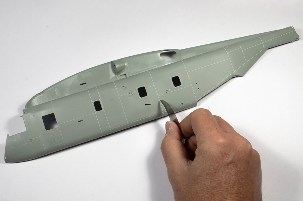

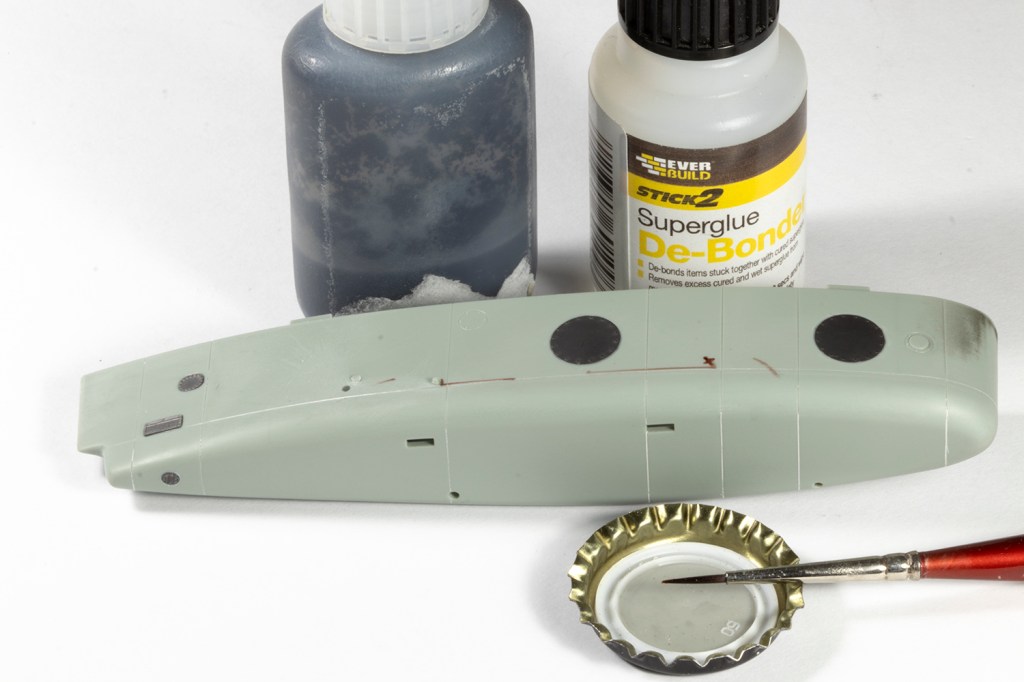
That meant getting the surfaces ready for some primer and rivets, which meant adding the Eduard PE bits and pieces first. I hate that gap that can appear between flat PE parts and the plastic they’re stuck to, so borrowed a technique from a very well known armour YouTuber (thank you Uncle Nightshift). This involves sticking the PE down with black CA and then very shortly afterwards using CA debonder to clean the joint up. Don’t do this over paint! Midway through I went to Scale Model World and bought the VMS black CA and debonder, which was an excellent combination for this task.
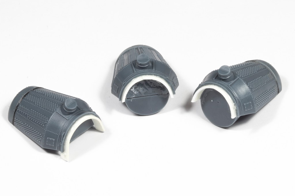
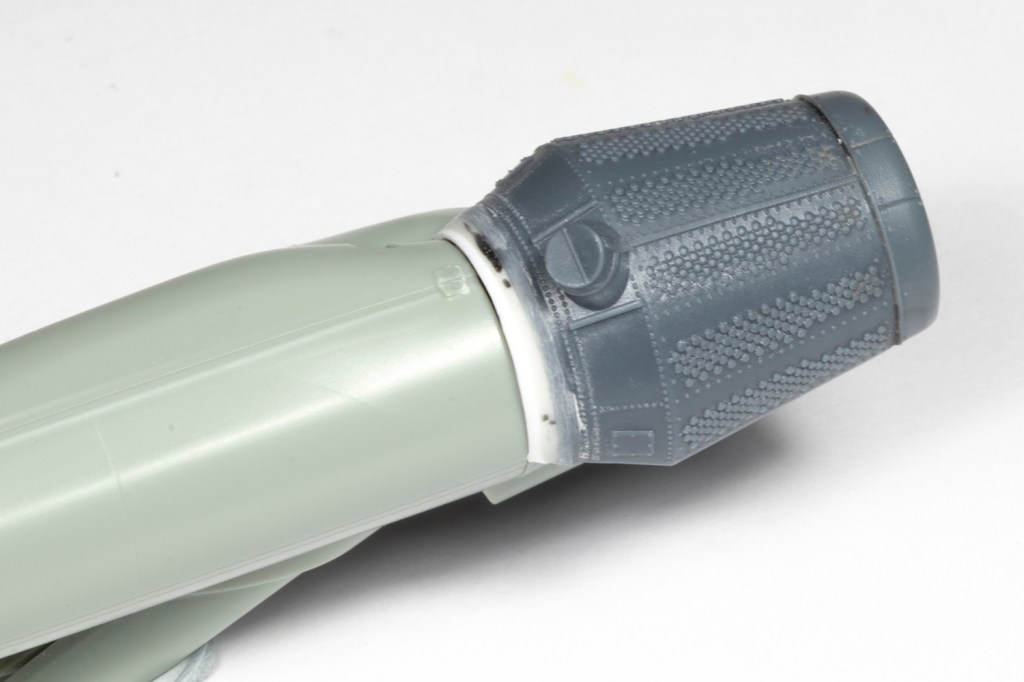
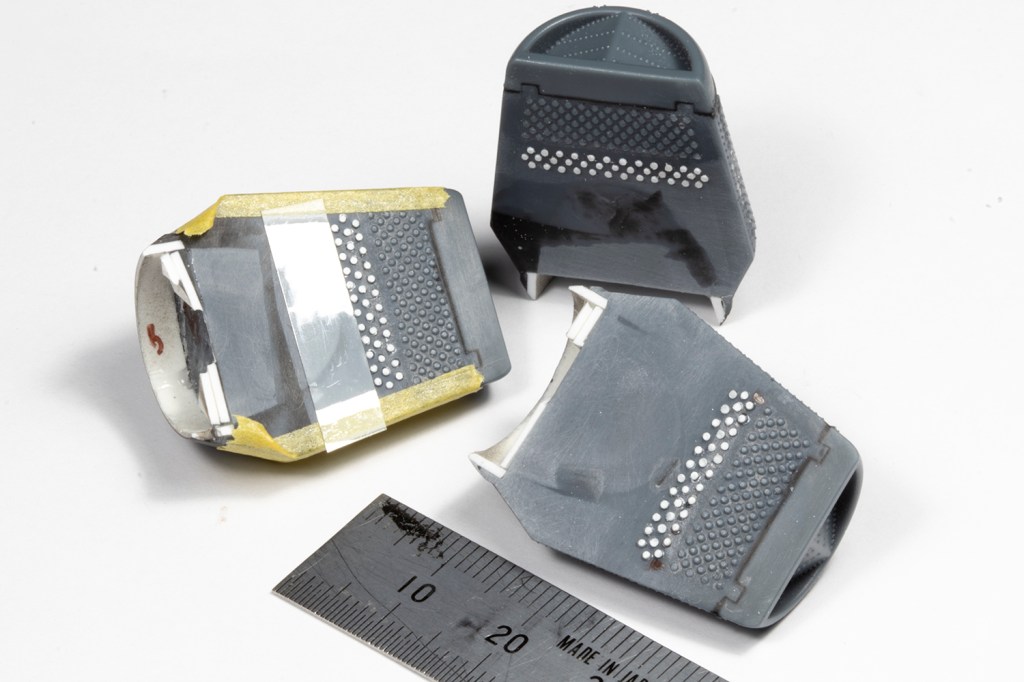
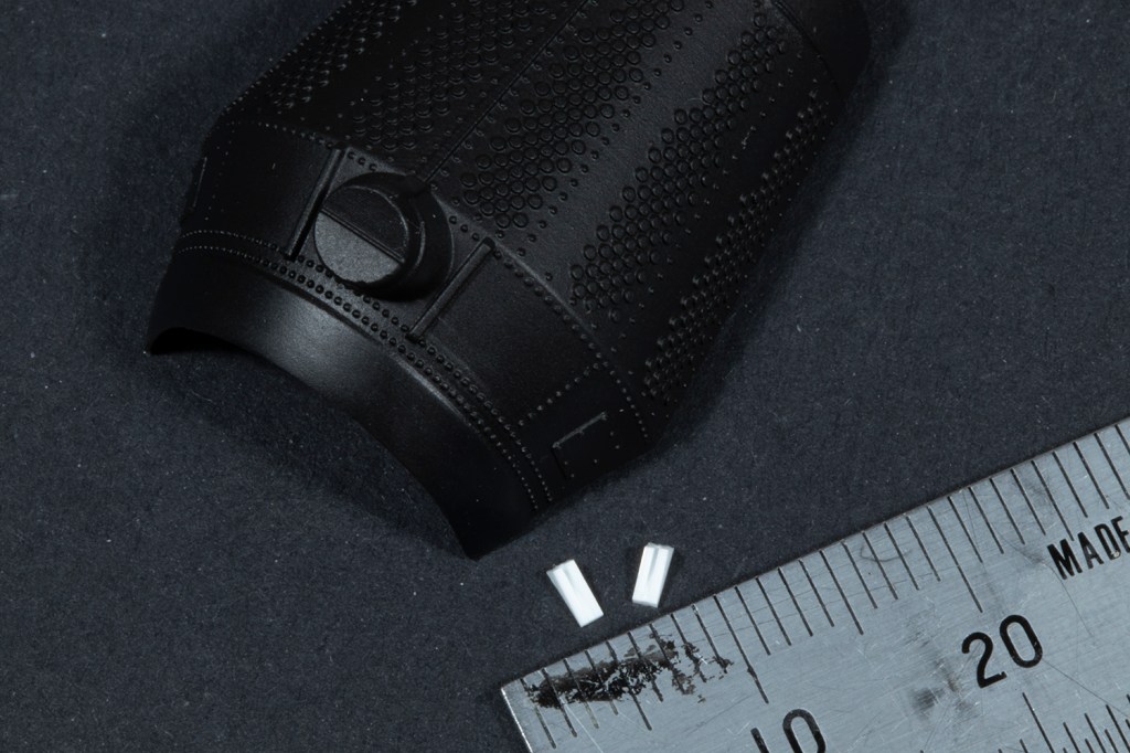
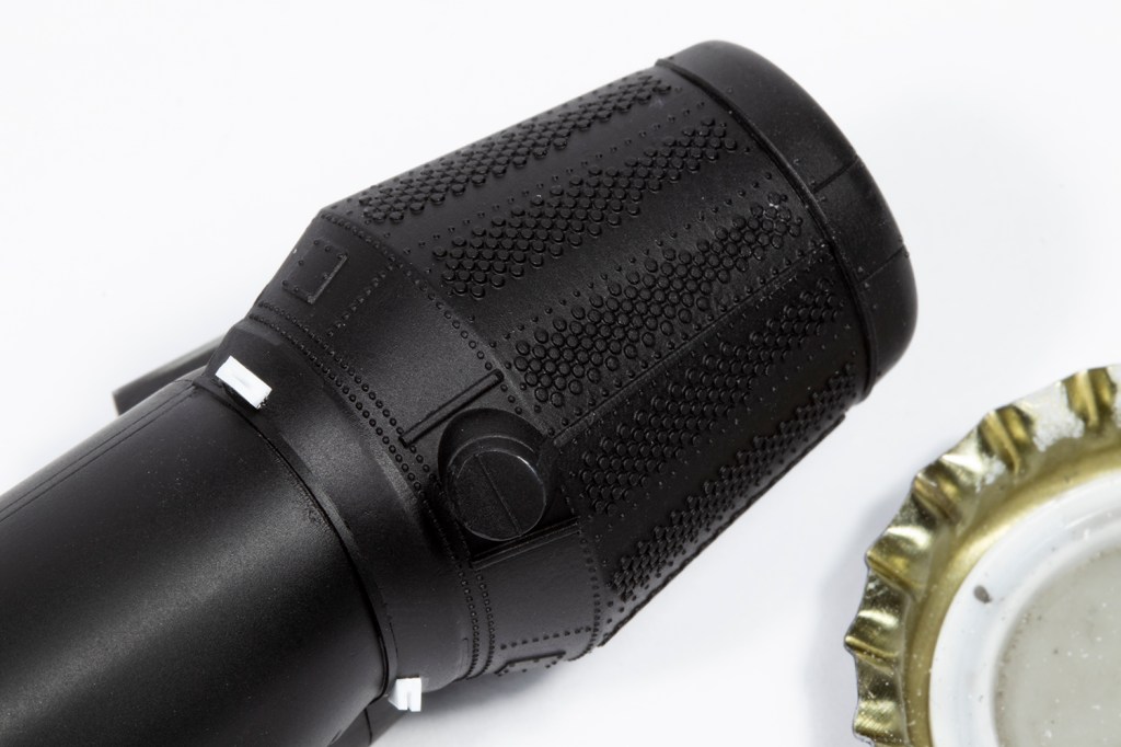
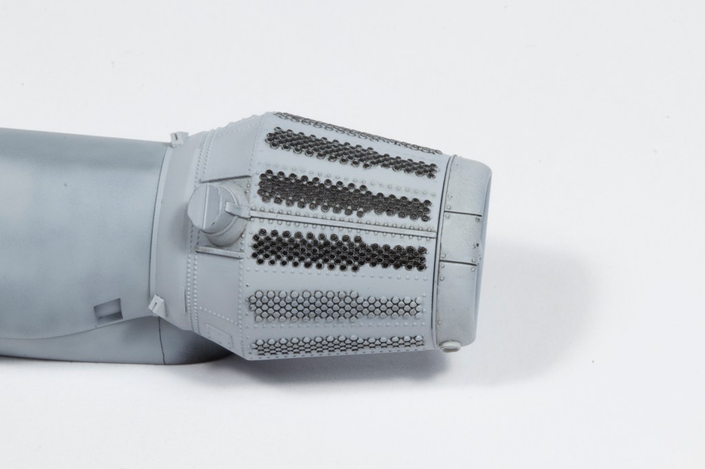
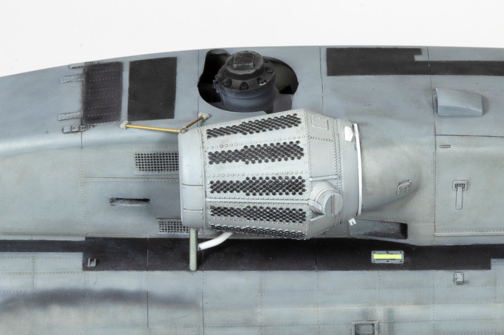
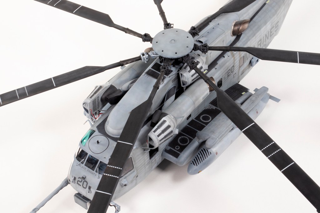
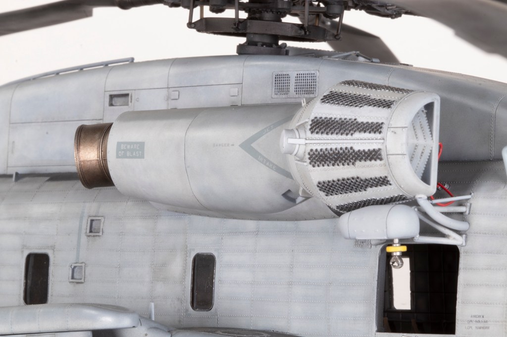
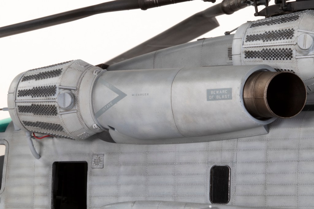
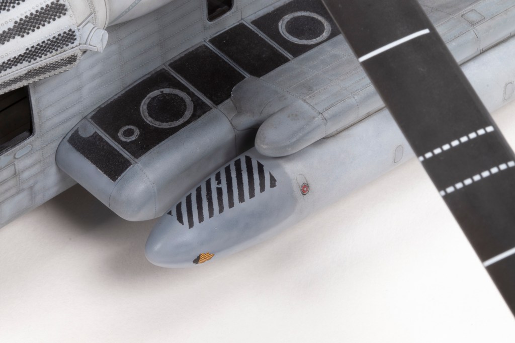
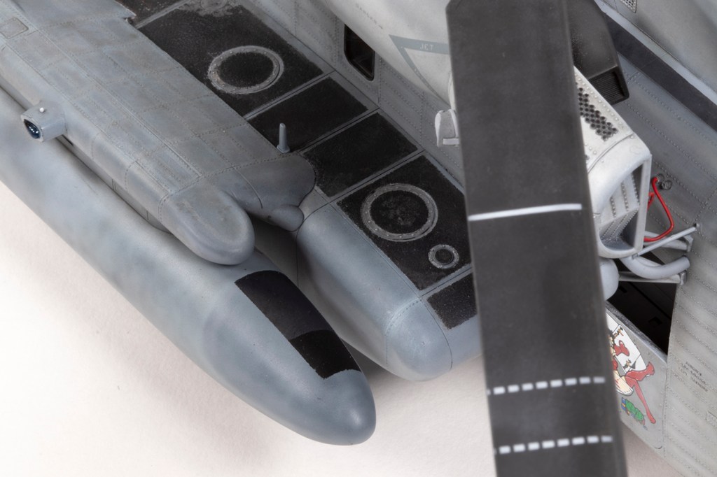
With the sponsons built up I started to mess around with the fuselage halves, which brought me to the ResKit intakes. I had been forewarned as to how bad these were and considered selling them, but middle-aged (I was going to write ‘youthful’, but who am I kidding?) confidence impelled me forwards. These are a terrible product and nearly brought the whole project to a premature end.
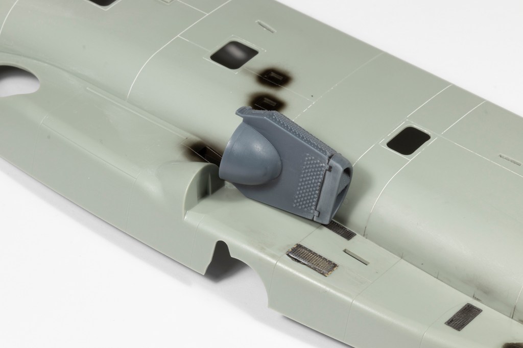
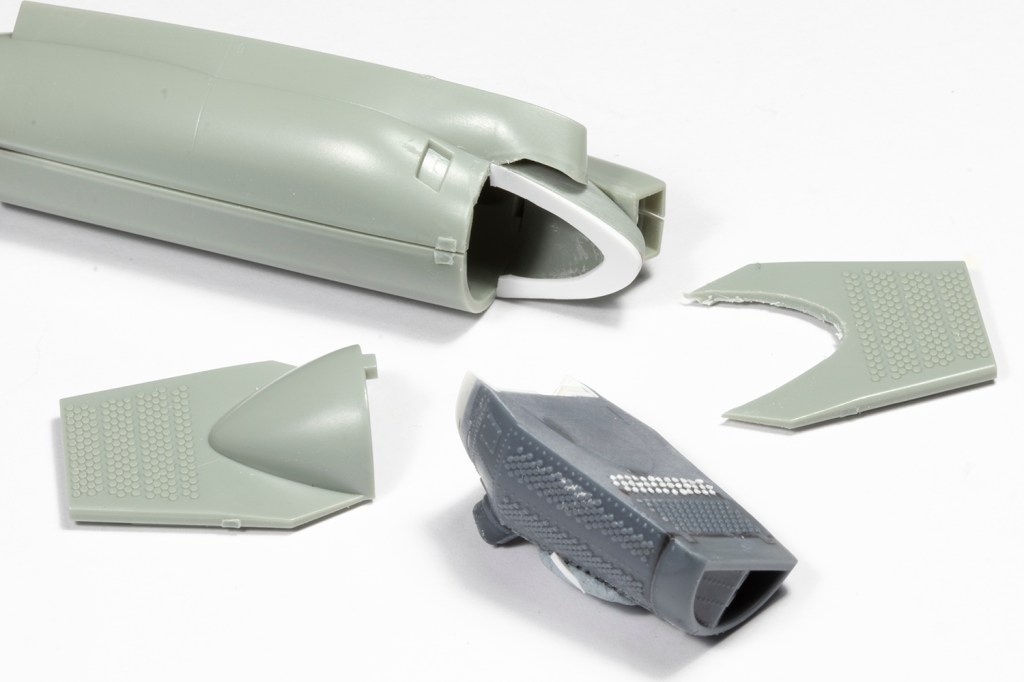
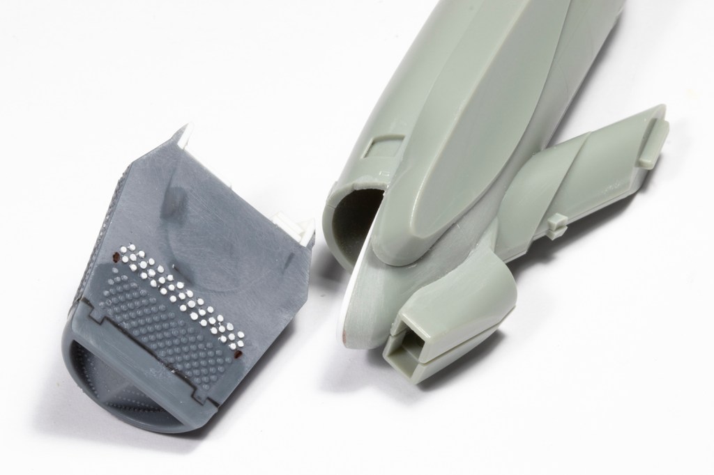
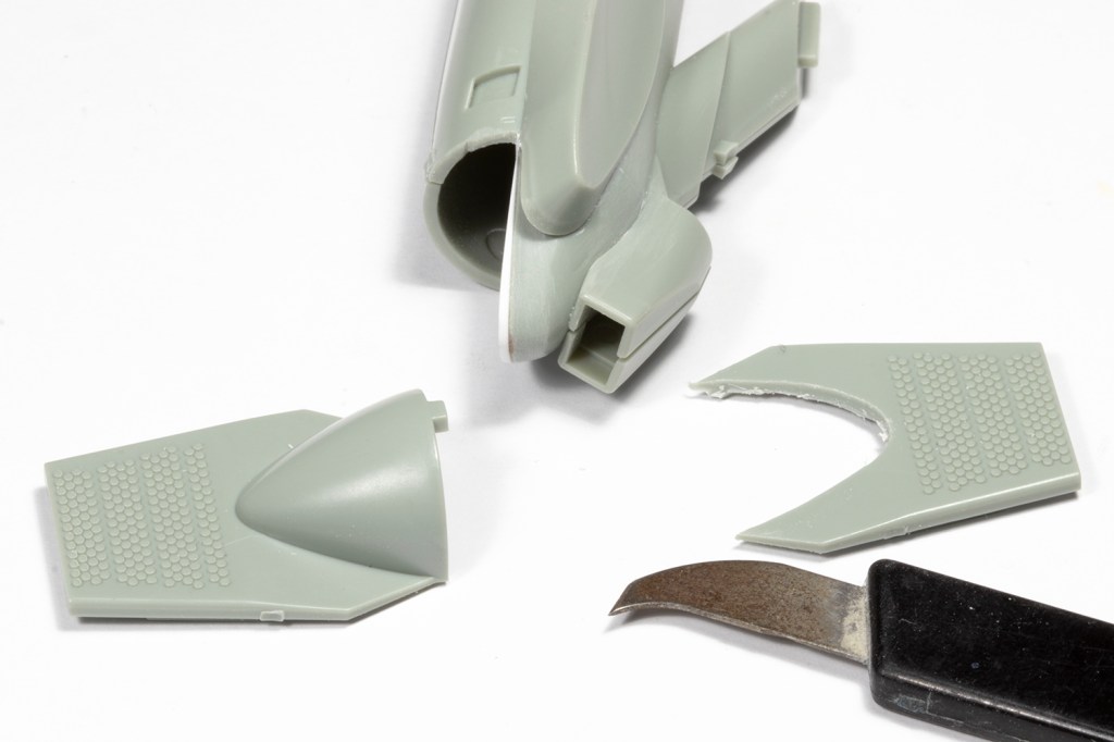
There are three engines: two are in external engine pods and the third is in the fuselage. As such, the way the intakes attach are therefore completely different. ResKit, however, give you three identical intakes, so the fuselage one doesn’t fit at all. Much hacking of resin ensued. The intakes are also much too wide at the rear. I cannot comment on whether ResKit or Academy are dimensionally more accurate, but rather than join fairly smoothly to the pods/fuselage, with just a very small lip, there’s a massive, massive disjunct. At this point I didn’t know what to do and was about to bin the resin parts, but they were rescued when I came across an incredible build of this kit by Bernhard Schrock on Scalemates. He documented how he solved the problem with little more than plastic card and superglue, so I was shamed into doing likewise.
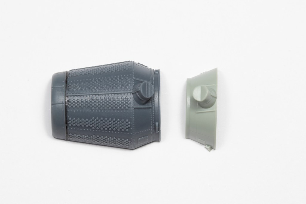
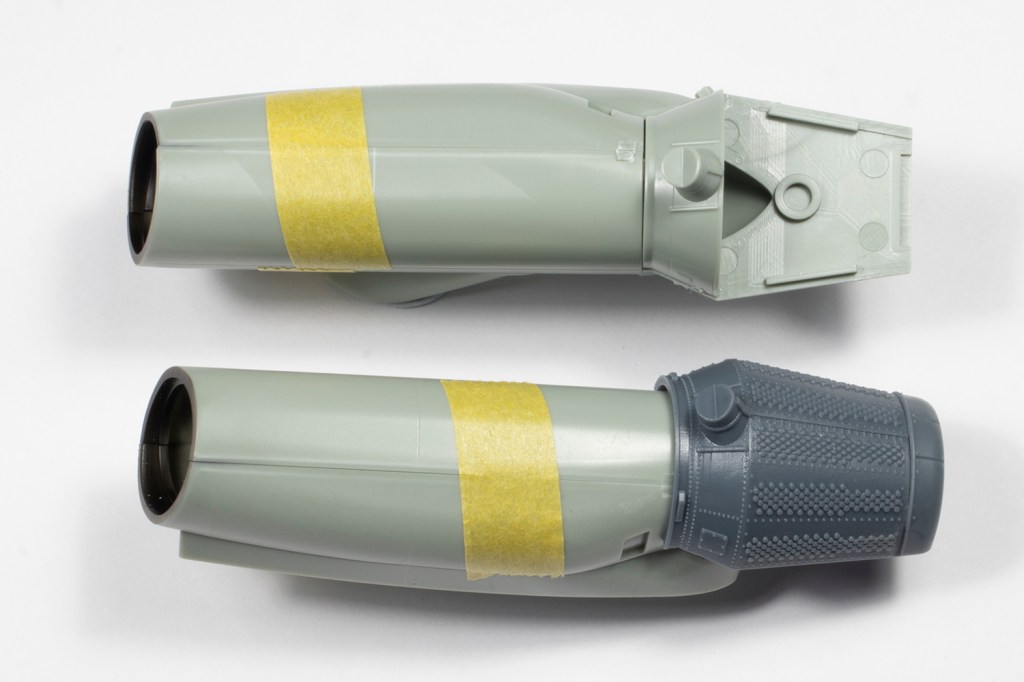
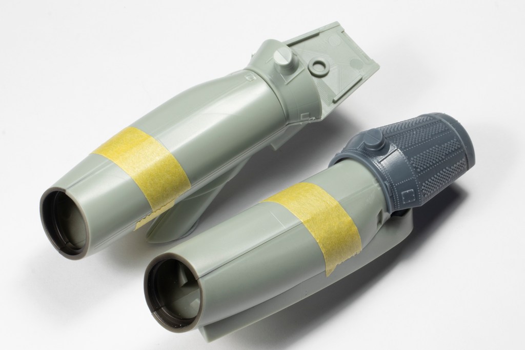
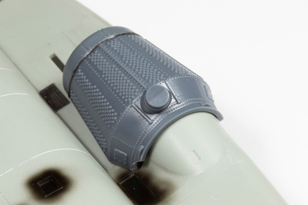
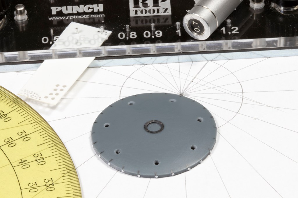
Thick rims of plastic card were superglued to the inner sides of the mating surfaces and the whole lot sanded down. Inevitably, some of the resin detail was lost. I also hacked off all the massive resin ‘bulges’ and decided to use those cut from the kit parts to aid fitting to the pylons. Circle detail missing from the inner faces (moulded correctly by Academy and Eduard!) was added by punching 0.6mm circles with a RP Toolz punch and die set. Eventually (and I mean ‘eventually’!) I had three useable resin intakes. Are they better detailed than what Academy supply? Just. Are they worth all this hassle? Probably not.

I was now about ready to now play around with resin rivets. Previously I’d used Archer Fine Transfers, but they’d closed, were extremely expensive and had carrier film to deal with. I invested in six sheets of HGW 1/48 resin rivets, and learned an obvious lesson: when experimenting, don’t buy six, just buy one. The advertised advantages were obvious: cheaper, much more in-scale and no carrier film, as these are ‘wet transfer’. However, they’re also a nightmare. I tried them out on the tail and immediately noticed how tiny they are. They have almost no relief and under the thinnest coat of paint they disappear completely. HGW advise you rub the paint back to reveal them, which does work, but only if you want to reveal silver rivets (since that’s the colour they come as). Silver against a medium grey paint is not going to show up at all. Not only were they invisible, they were extremely difficult to apply. I ruined an entire sheet when the wet transfer film came away with the protective tissue cover. When I did get them to work, random rivets would float off and do their own thing. Sometimes no rivets at all would come off with the transfer film; sometimes they’d have all disappeared into the decal water before the film even was moved. I’m sure they’re a great product and can be used by an appropriately skilled modeller, but I am not he. I abandoned them for Eduard.
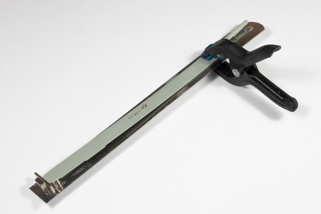
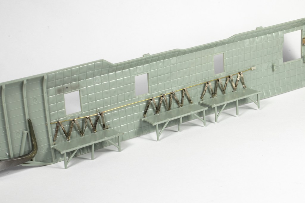
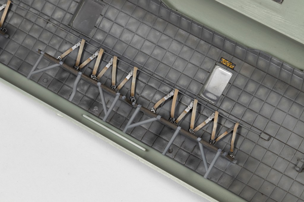
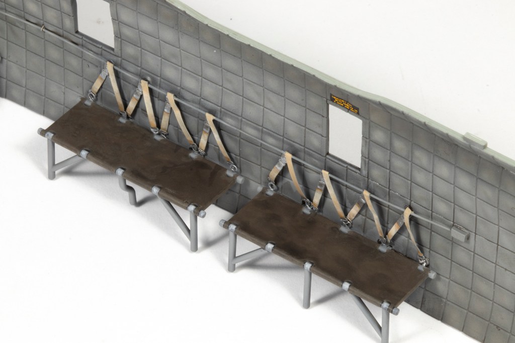
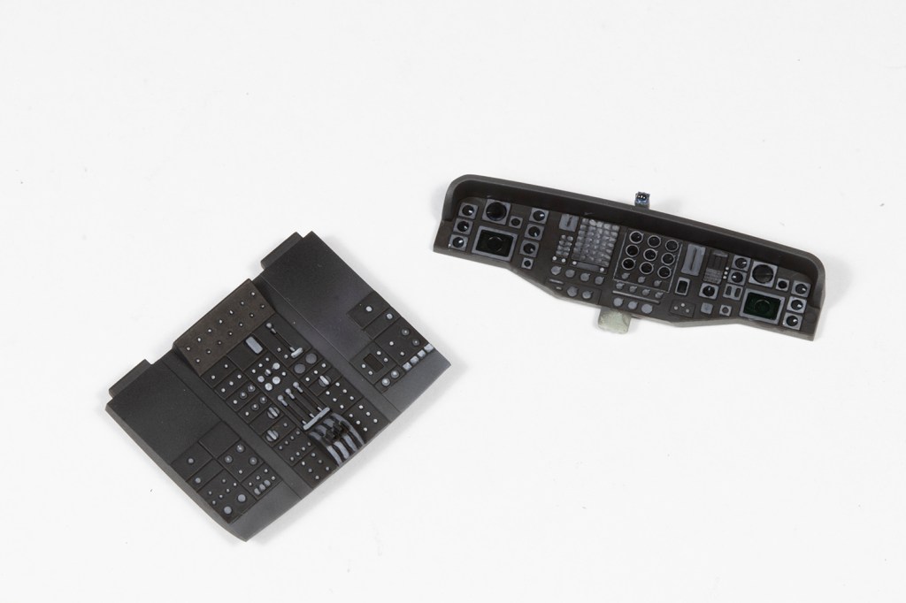
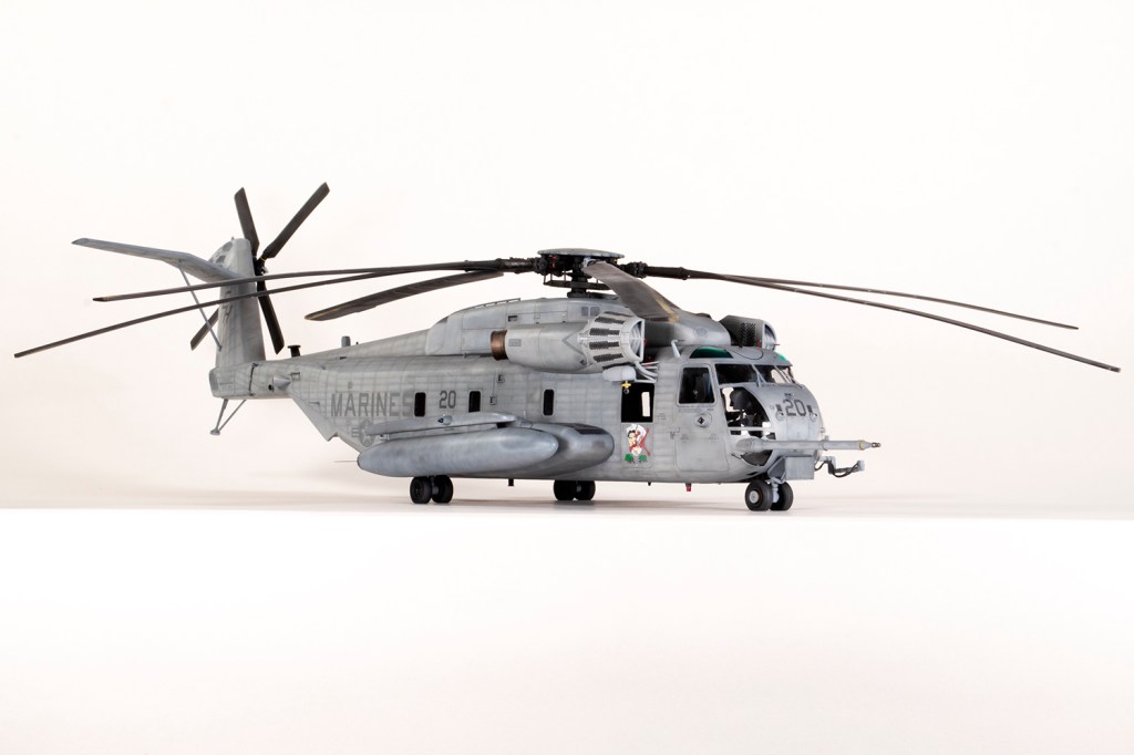
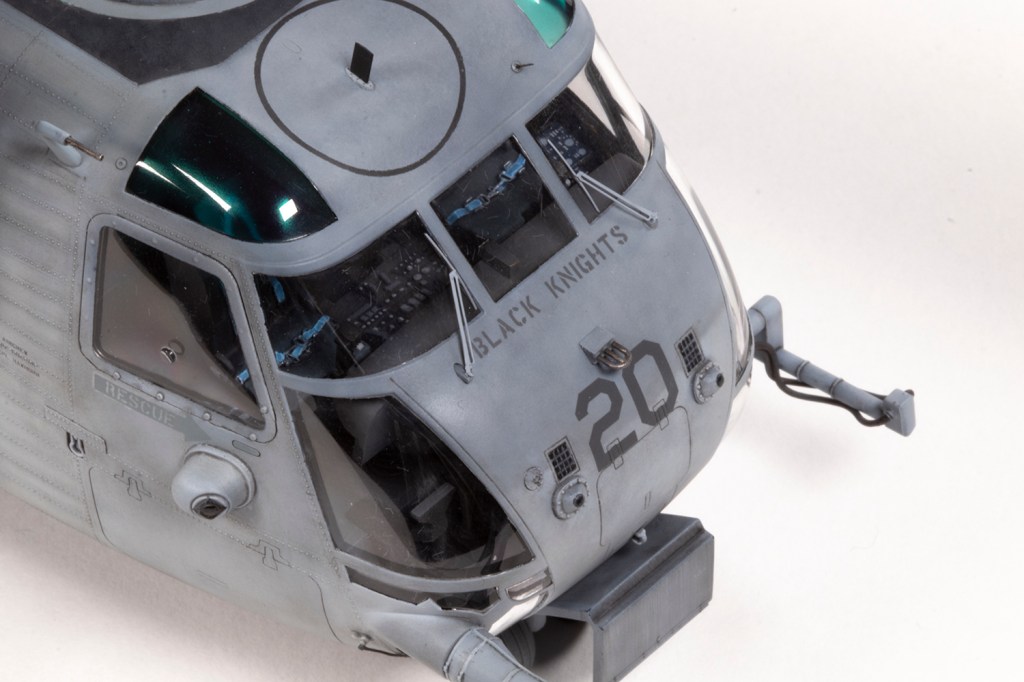
While waiting for Eduard resin rivets to arrive, I finally turned my attention to the interior. This would be from the kit and Eduard PE. Inevitably, the insides are massively simplified, and since I was closing the rear ramps and visibility would only be through the front two hatches I didn’t need to bother that much. You could really go to town in the cockpit, which is much more prominent, especially around by the pedals, but I didn’t and simply added what the sets provided. Because they are more three-dimensional, I tend to prefer having a go at painting the instrument panels even though they are less detailed than the pre-painted PE. The cargo bay seats are an older style that was replaced around about the timeframe in which I was modelling this CH-53, so they may well be very inaccurate, but the Eduard set adds some moderate visual interest if you make the effort to look. The belts are difficult and complicated to install so I soldered them to a brass rail for some extra strength.
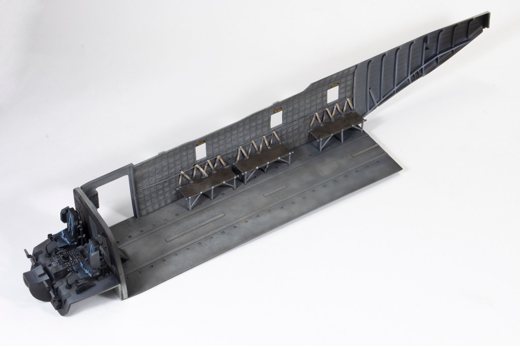
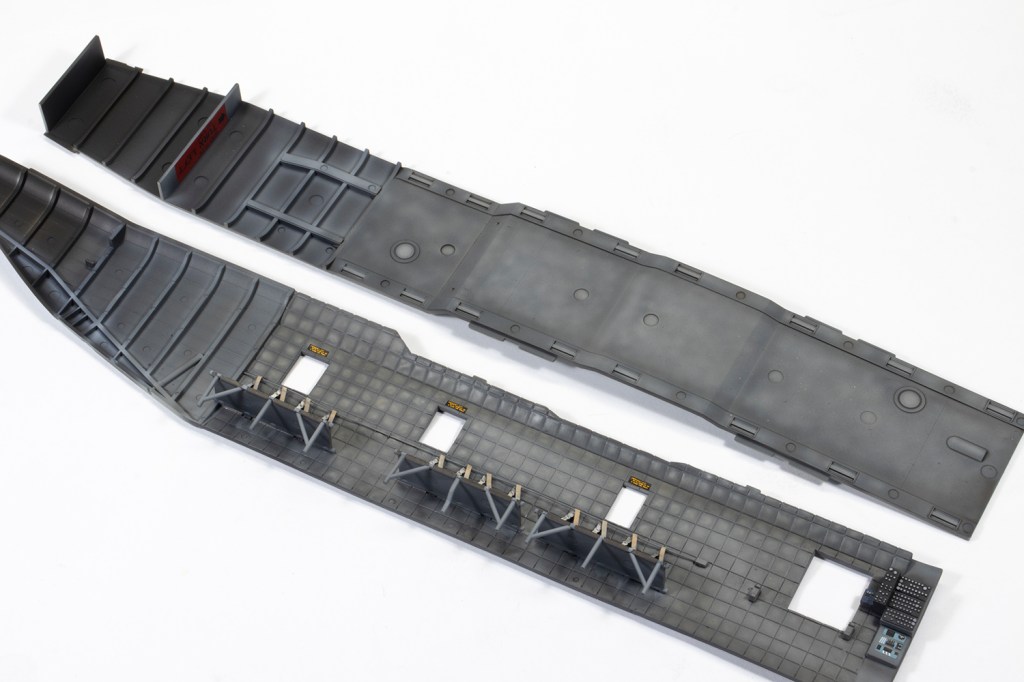

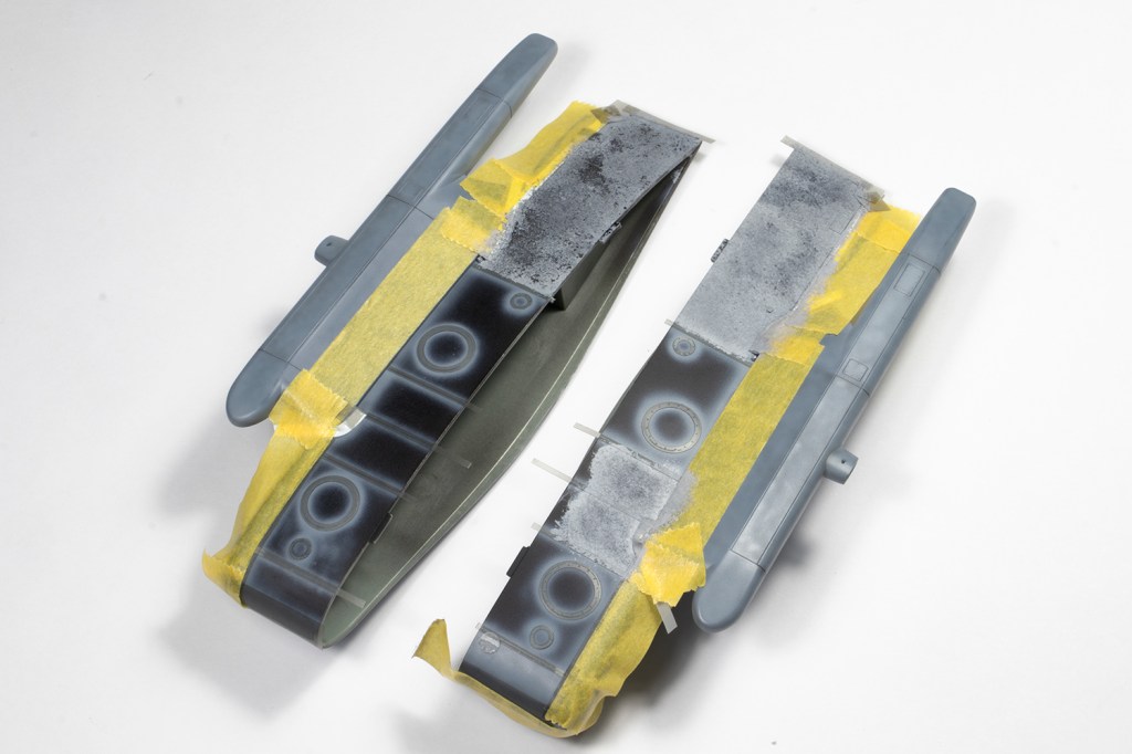
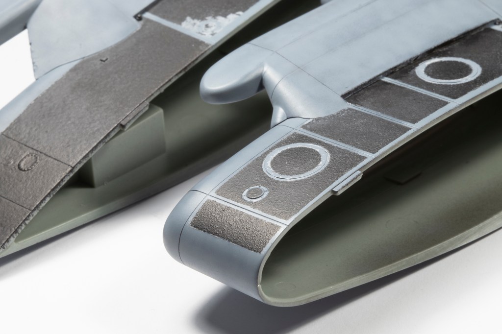
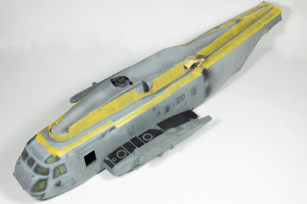
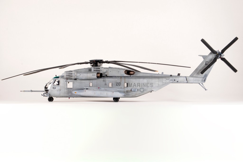
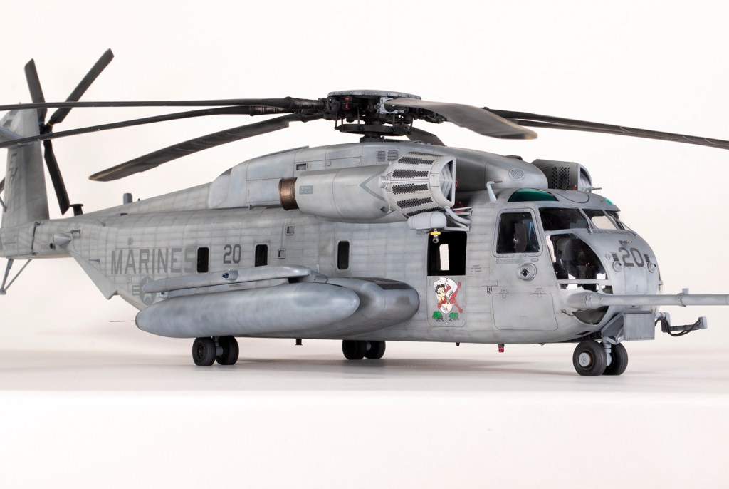
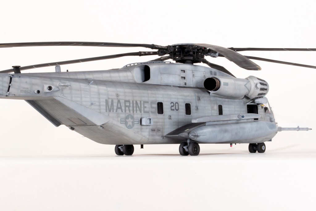
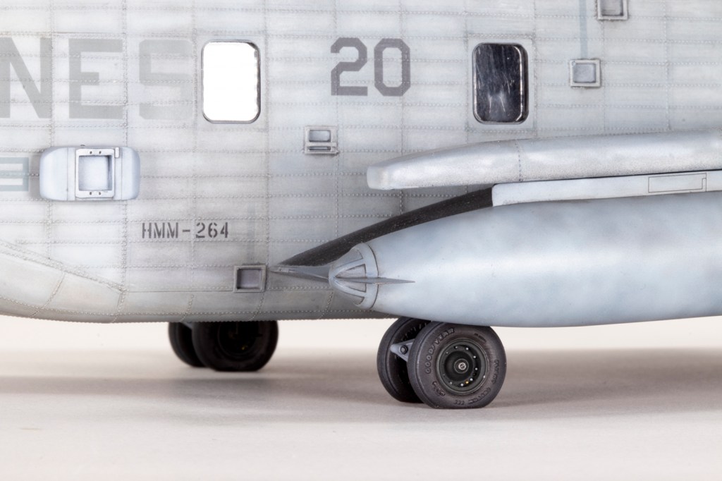
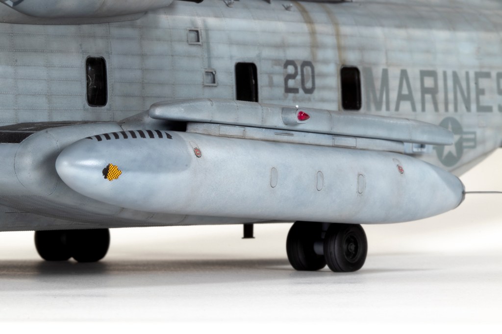
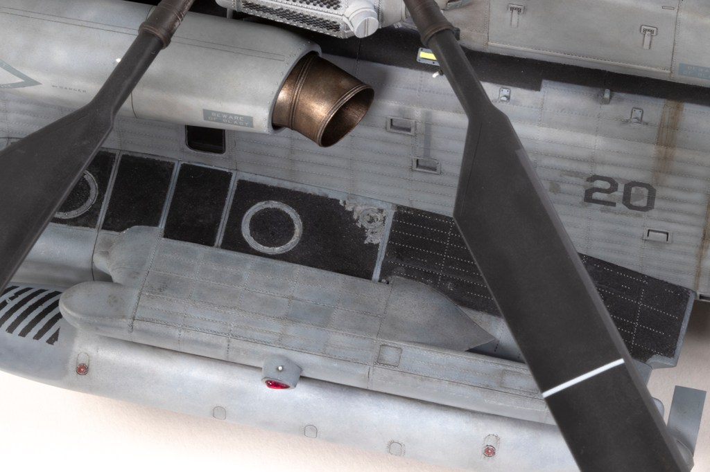
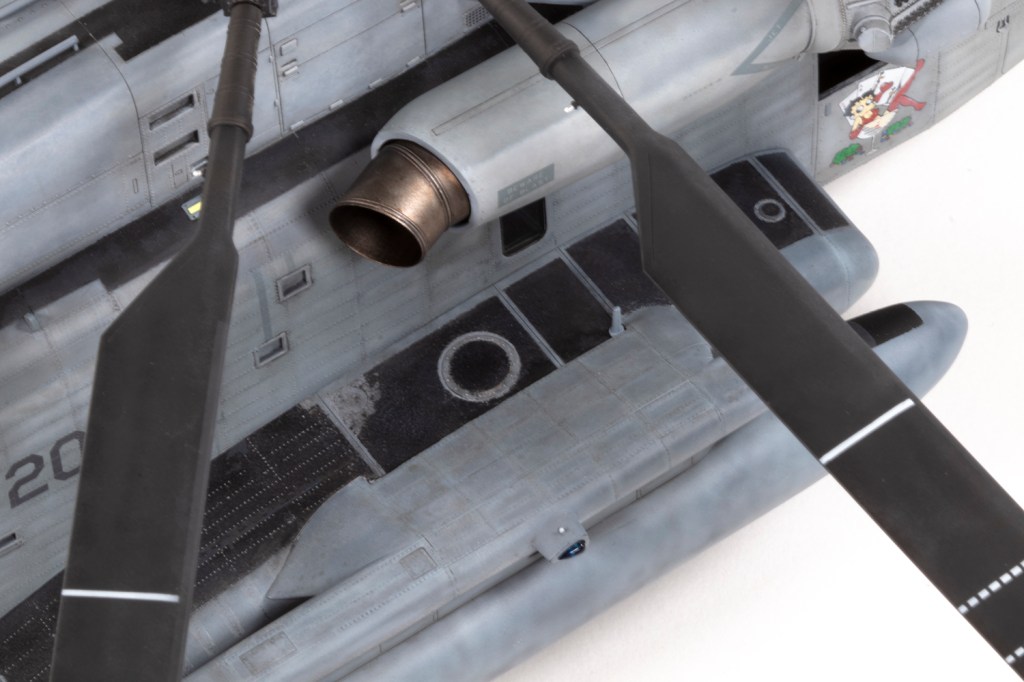
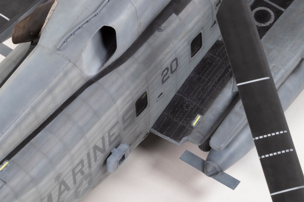
In parallel with the interior I was making the large fuselage pods and fuel tanks with their ‘bat wing’ mounts. I noted from photos that the walkways could get very grotty and were often messily applied. In an attempt to give a flavour of how rough they were I masked them out with some vinyl and daubed on a thick coat of Mr Surfacer 500. Over the top of this went some sponged dark grey Vallejo acrylic paints mixed from black and white. The overall effect was a little exaggerated and there was some leakage under the masking, but I was happy enough. For the walkways I subsequently painted on the fuselage I toned the texture down a bit by using Tamiya tape as the mask and applying less of the Mr Surfacer. Photos also showed some prominent exposed rivets on the walkways, and finally I found a use for the HGW rivets to represent these. The fact that random rivets would go missing added to the effect as they were not uniformly visible in real life since the anti-slip covering wore away unevenly.
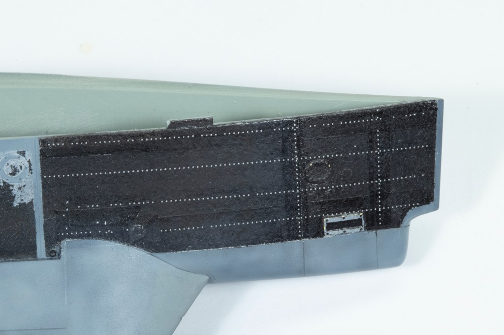
Finally my Eduard rivets arrived and the real slog of this build could begin. I had no idea how many I would need: the answer is four sheets for those of you insane enough to try this. With hindsight I should have used some double rivet rows for greater realism and visual effect; I got so bored with the process I was pleased enough to do what I did with single rows.
Prior to joining the fuselage halves I wanted the centre sections rivetted and finished. The Eduard instructions are a little confusing, but essentially I dipped a cut strip of rivets in a pool of water with some washing up liquid, and laid it to rest on a soaked sponge. Mr Mark Setter was used as a setting agent with the decal strip applied over the top. I then simply left the rivet strip to dry out. I was concerned about adhesion, and had to plan the build such that I never ended up masking over the rivets, or sanding, which was more difficult than it sounds. Someone suggested running some Tamiya Extra Thin over the rivet decals to remove wrinkles and bubbles, and I was gobsmacked to discover this was a Good Idea. Go easy with it though! In actuality, I did end up gingerly masking in a few areas and I found the decals surprisingly robust. In some areas where I wanted a different pitch, I used some Archer rivets I had from a previous project. These are more fragile. In short, the Eduard product is good, but there is still the inevitable decal film which I could not eliminate.
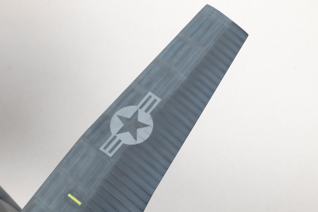
The riveting process can be made less stressful by marking out the rows in pencil beforehand. It’s actually quite hard to get lines parallel and evenly spaced, and to determine the pattern in quite a few areas, especially around the tail. I didn’t get them parallel or even and hoped this would be lost in the overall effect at the end. All told, the rivets are not particularly accurate and took absolutely ages. I’m not anxious to do it again.


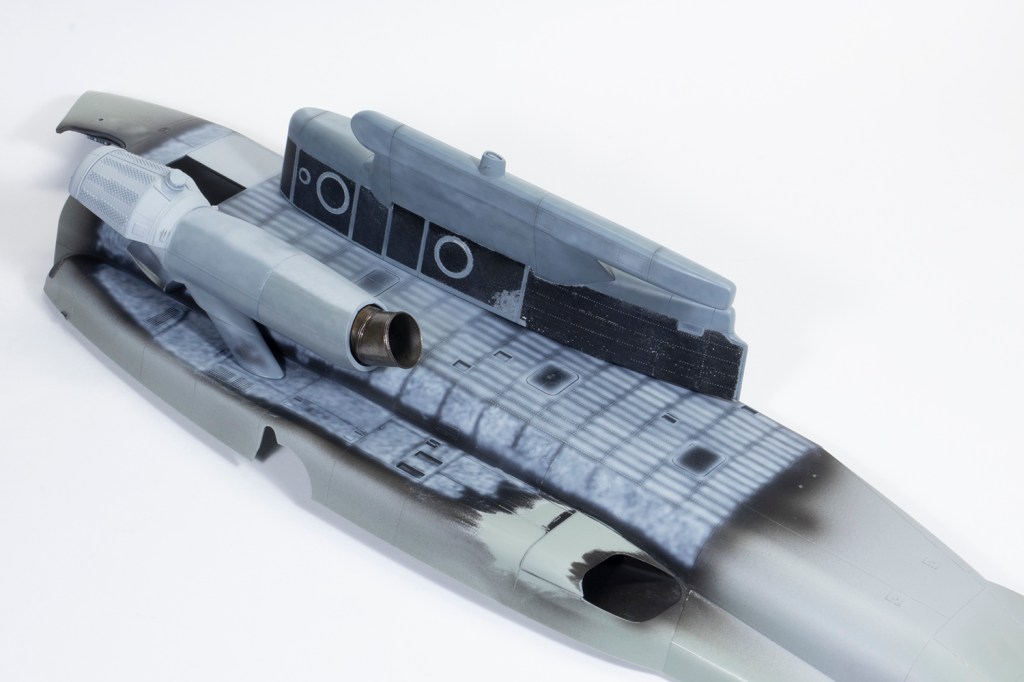
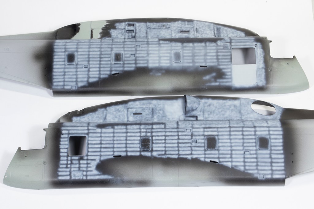

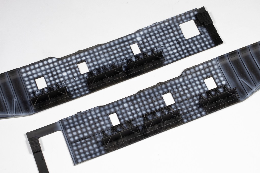
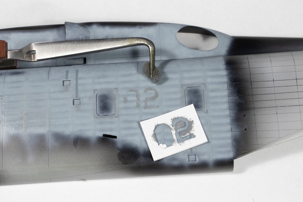
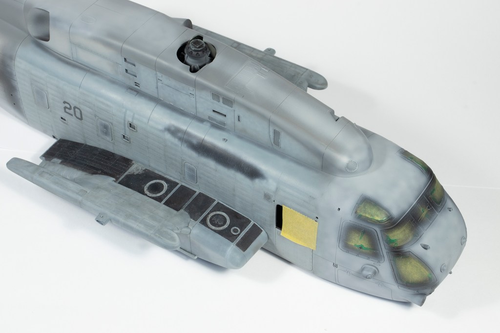
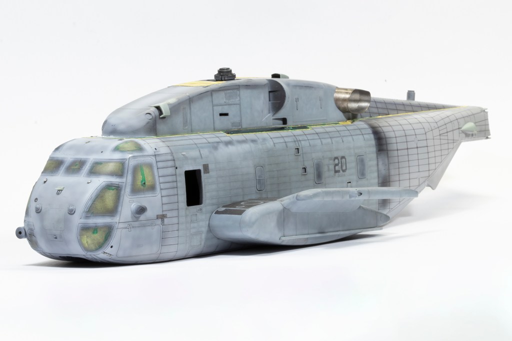
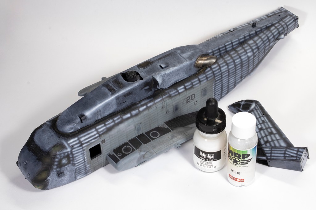
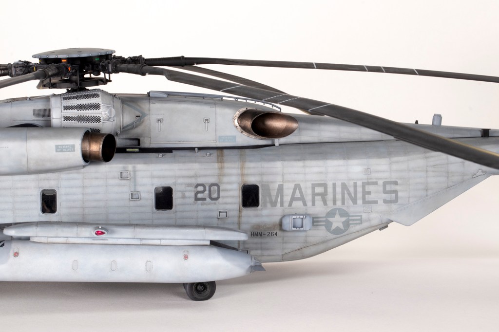
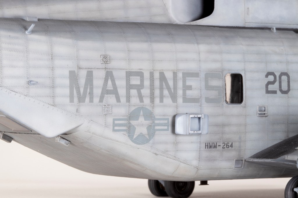
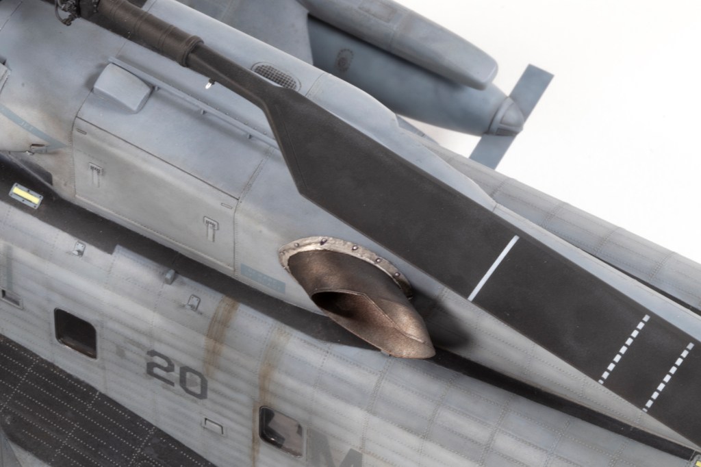
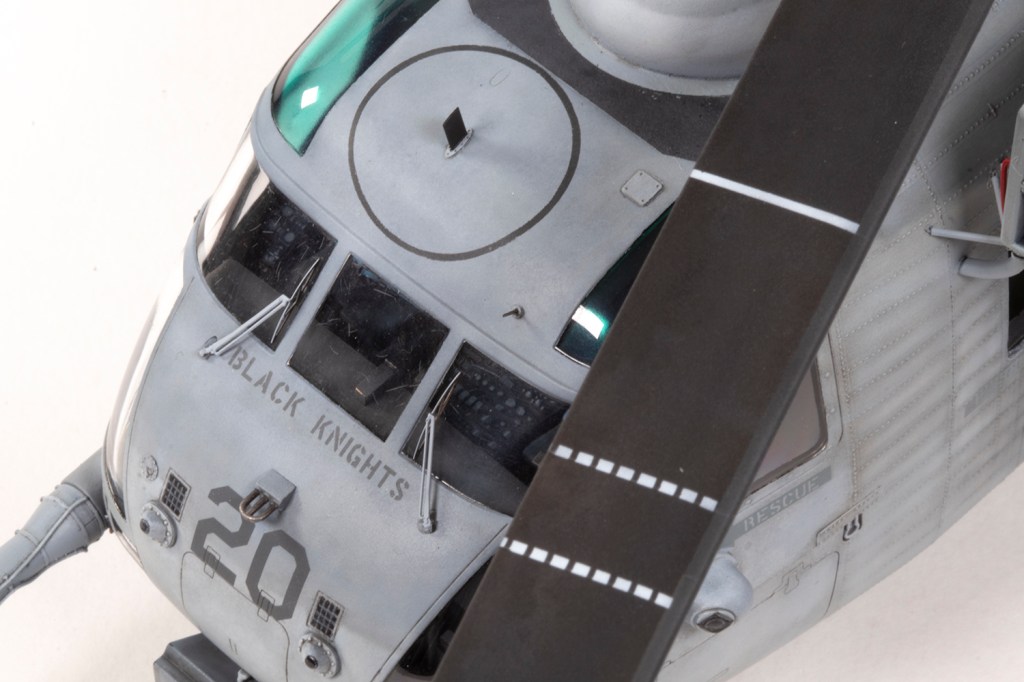
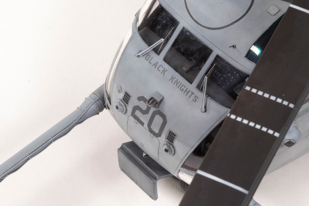
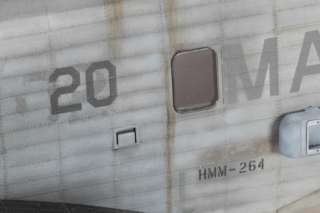
The centre sections were all painted (with various shades of FS36375) using a black primer and white highlights to generate a more interesting finish. A neat detail of this airframe was that the number ’20’ on the port side was painted over the remnants of the previous number, ’02’. This was not present on the other side. I made a paper mask for the ’02’ and sponged on some dark grey acrylic paint to represent the older marking.

The time to join the fuselage halves eventually arrived, but I needed to figure out how to mount the rotor base. ResKit provide absolutely nothing – it just floats in space – and a combination of spare parts from the kit were stuck to the cargo bay roof until I found a position I was happy with. I then joined the halves using super glue and began to appreciate just how massive this aircraft is.
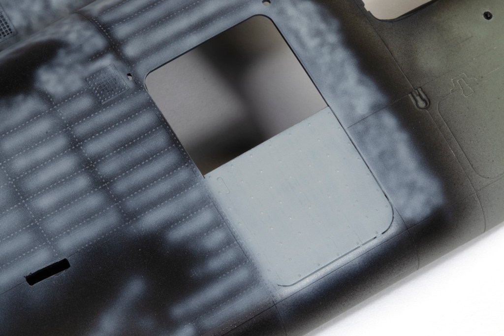
The fit of the major fuselage parts was adequate with all the joints requiring a fair amount of filling. Spending time with them, particularly the large underside panel, served to show again how simplified the detail is. Eduard supply some PE parts to rectify this, but it’s really a drop in the ocean. For attaching the various PE parts I used Deluxe Materials Super ‘Phatic glue for the first time, which looks like a runny, shiny PVA but is marketed as a CA alternative. I was seriously impressed by how quickly it set, with more time for adjustment than super glue, combined with easy water clean up and excellent sticking power.
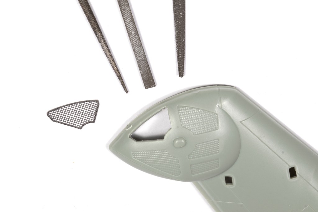
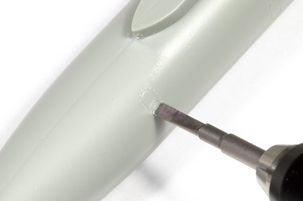
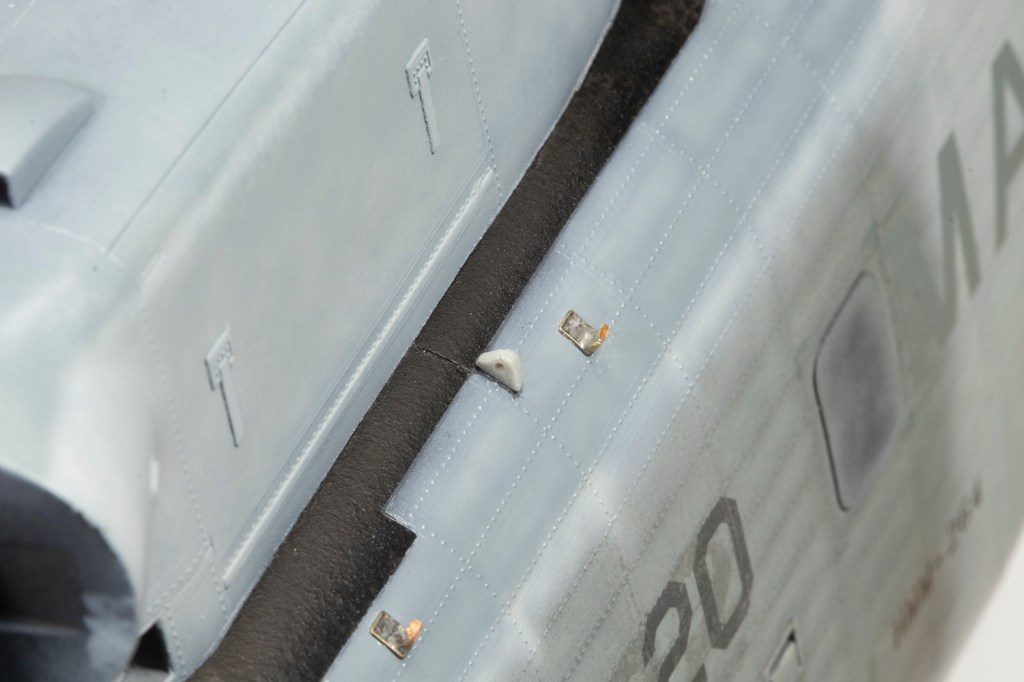
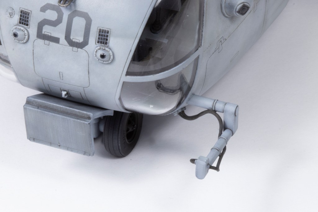
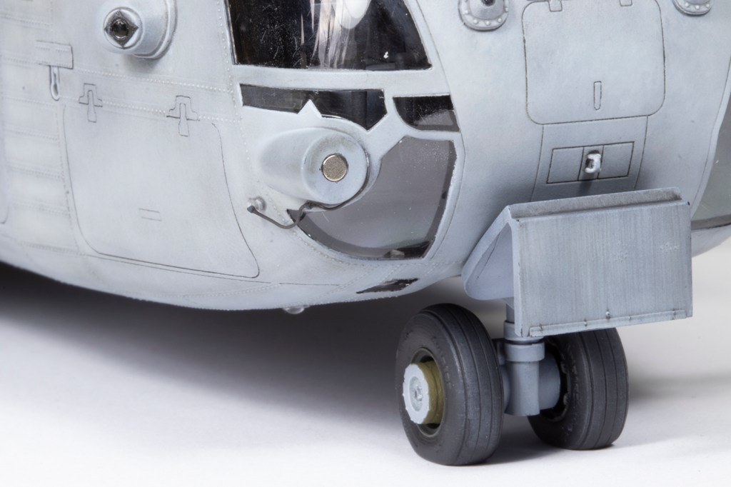
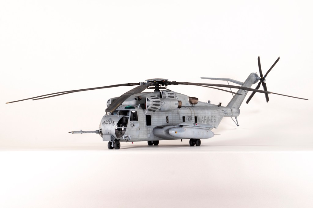
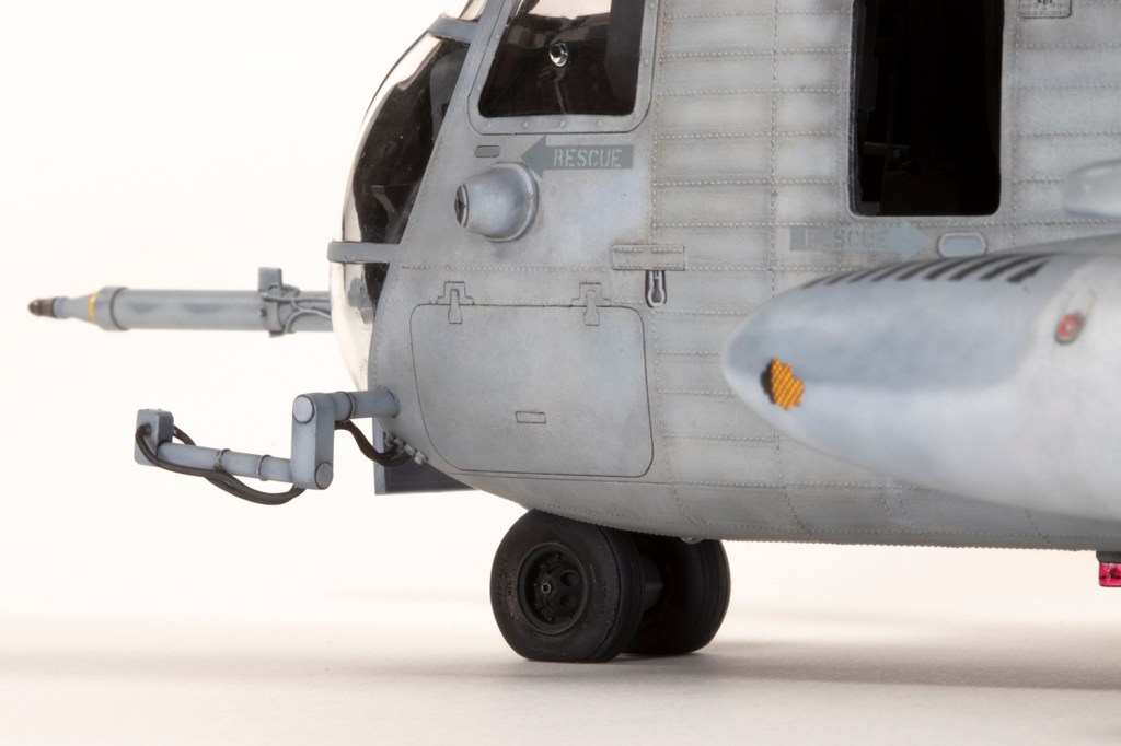
I couldn’t live with some of the missing details, particularly the large enclosed lights to the side of the nose wheel bay. As I always do I eye-balled the dimensions and locations and used some Tamiya vinyl tape to mark out their shape. I cut them out using a scriber and scalpel and then boxed them in – it would have been infinitely easier had I decided to do this prior to joining the fuselage together. Once sealed, clear UV resin was poured in, set with UV light, and then sanded and polished. It’s a bit baffling why such an obvious feature was missed…

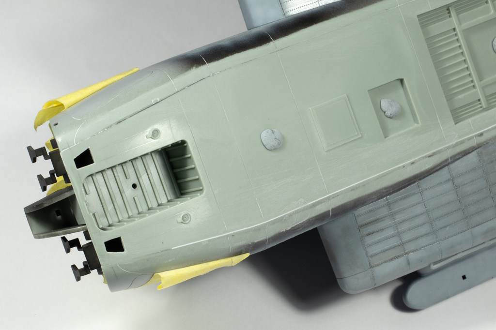
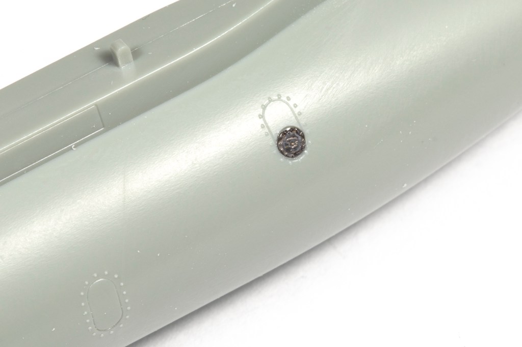
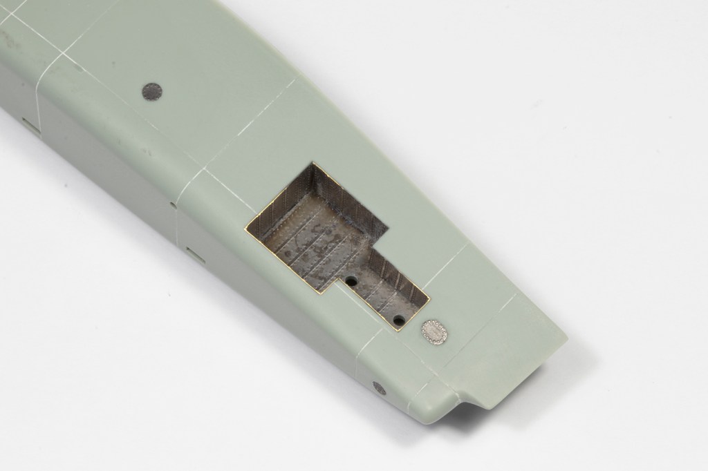
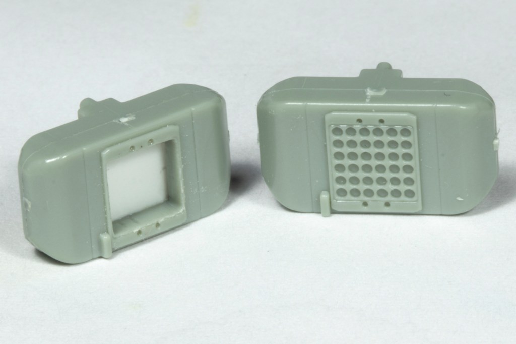
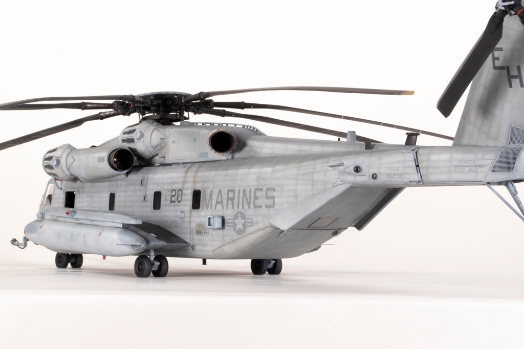
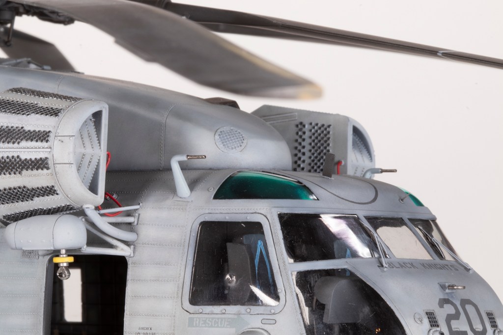
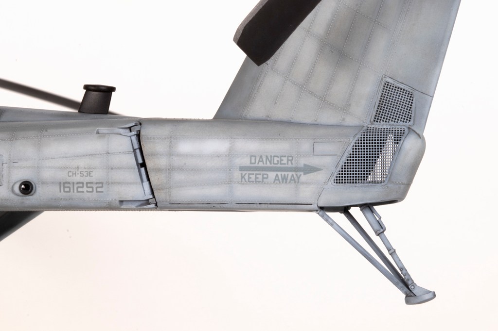
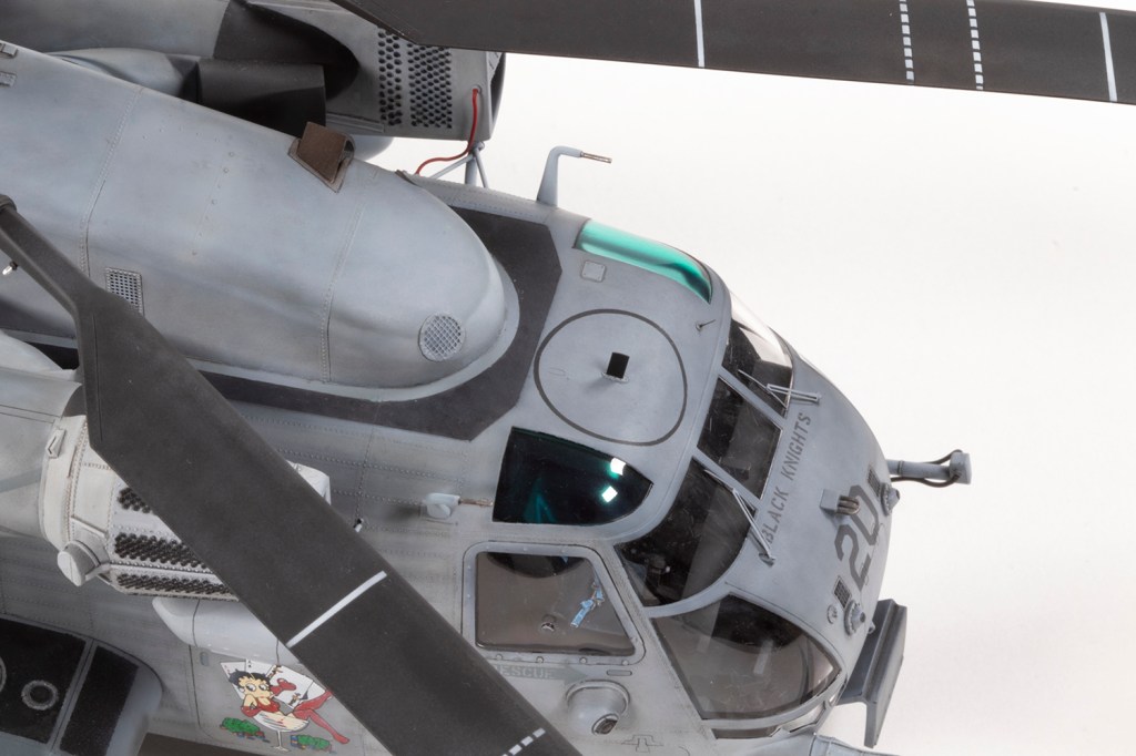
Close examination of photos threw up lots of little modifications I needed to make. The chaff dispensers had the cartridges cut out and the space blanked of with plastic card. At the front, the night vision FLIR sensor, which usually sits at the end of the arm that sticks out, wasn’t installed and I needed to cut it off the mount. The cables connecting it to the nose were still present and added with lead wire plugged into ANYZ resin connectors I added to the fuselage. A GPS sensor, which looks like a stumpy pole sticking out of the rear fuselage spine, was created from plastic tube and a box from the spares box. As is invariably the case with my additions, it’s a bit overscale. UHF aerials needed to be added top and bottom (modelled using spares from Hasegawa A-4 kits) and I think the sensors on the nose are shown the wrong way round in the instructions, but don’t quote me on that. They do, however, show that most of the moulded detail on the nose is wrong in location and size.
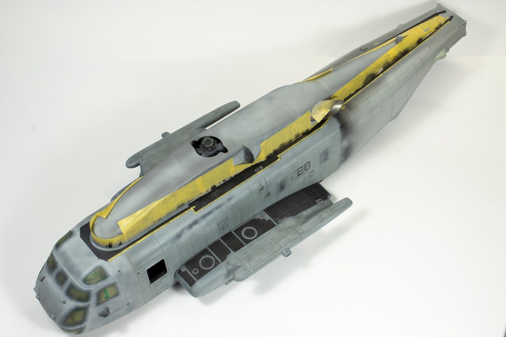

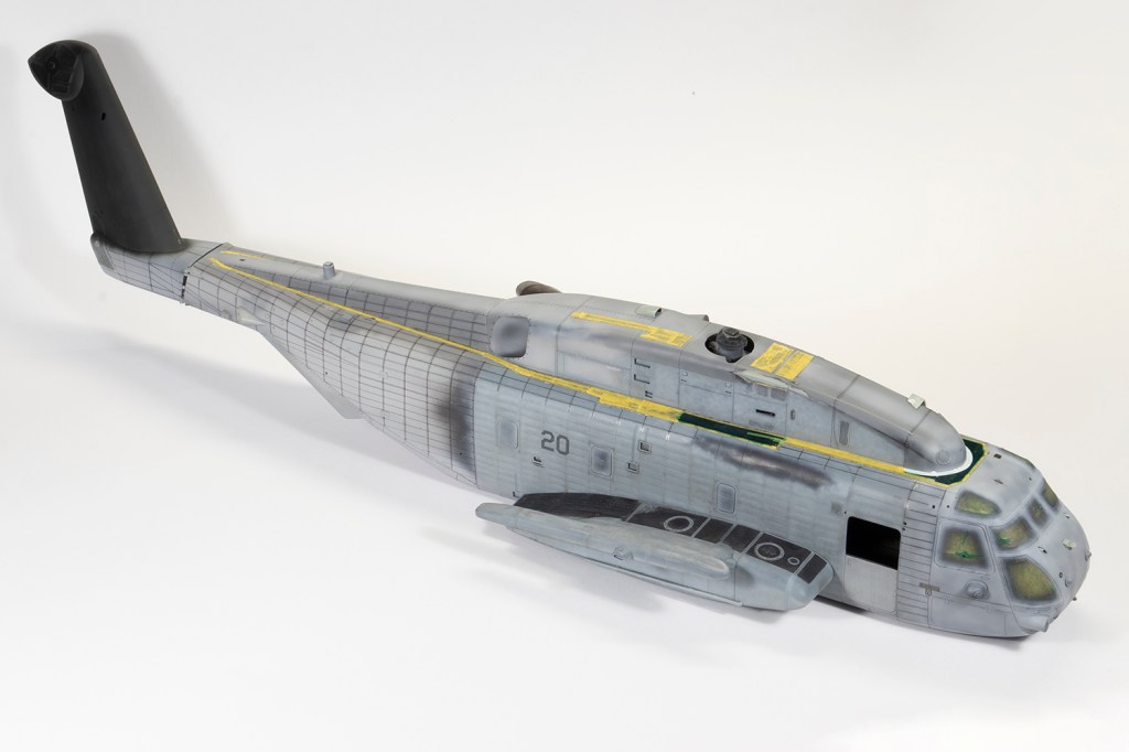
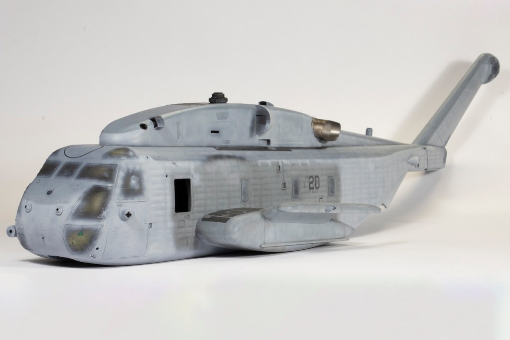
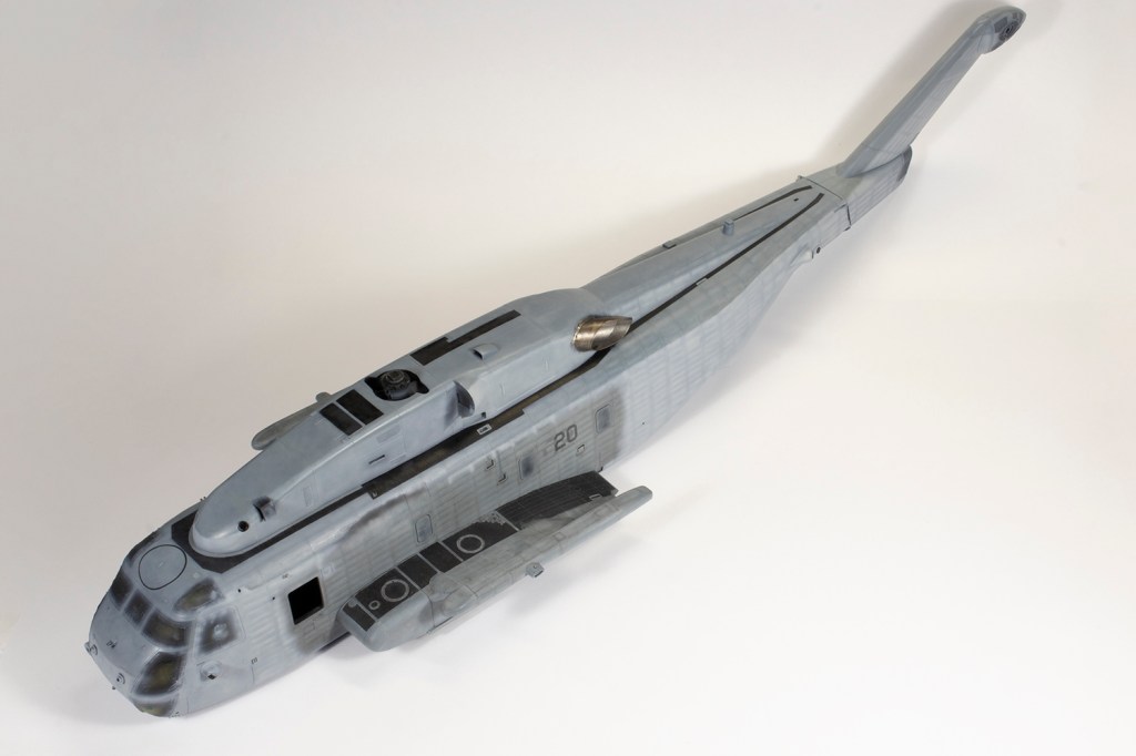
With the main fuselage completed, riveting and painting could recommence. This was just repeating what I’d already done for the centre sections, although I wish I’d written down in detail the previous steps so the rest of it could blend in properly; as it is, the centre section is a slightly different tone to the rest of the airframe, although the effect is subtle and adds to the overall grubbiness of the finish. The paints are all variations on FS36375 and 35237 by MRP, SMS, Mr Color, Hataka and AK Real Colors. The main ones used were by SMS, which claim to be airbrush ready. However, for the conditions I was airbrushing in, I found I got much better performance from them by thinning about 30% with Mr Leveling Thinner and adding a drop of Mr Mild Retarder; spraying neat resulted in spitting, but the thinned paint went down much smoother and still with excellent opacity.


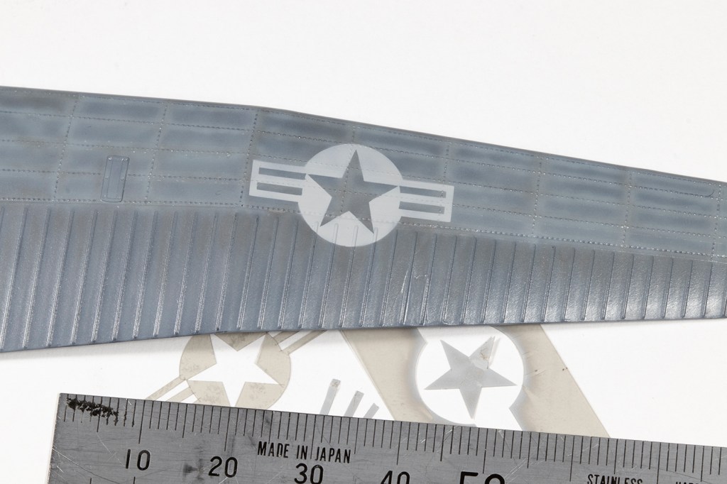
Decals can be mentioned in brief. The main scheme comes from AOA Decals, and they are beautiful. The sheet covers CH-53s, CH-46s and AV-8Bs from USS Bataan in 2006, and to fit everything on AOA forewent the generic markings that could be used from the kit. This meant there are no stencils and the national insignia and intake warning markings are the Academy decals. The latter are adequate, being nice and thin and respond well to decal solvents, but did have a tendency to fragment. It’s a shame AOA did not include the stars and bars as the Academy ones differ slightly in colour from the AOA MARINES markings, and the kit stencils are not accurate for this timeframe. I believe someone is developing a full sheet of accurate stencils, but sadly too late for my model. There is no national insignia of the appropriate colour in the kit for the tail and mine had to be masked and sprayed.
I’ve no idea why, but it never occurred to me to dry fit all three engines at once earlier. Had I done so, I would have discovered the two engines on the port side foul each other, another consequence of the ResKit intakes being too big. I did the best I could and used strip plastic to try and hide the gap. The kit-provided struts between the fuselage intake and the fuselage itself were replaced with plastic rod and brass tube and several missing struts added. There should also be struts between the engine pylons and the fuselage but after spending an inordinate amount of time figuring out how to add them I gave up: I simply could see how to access the area.
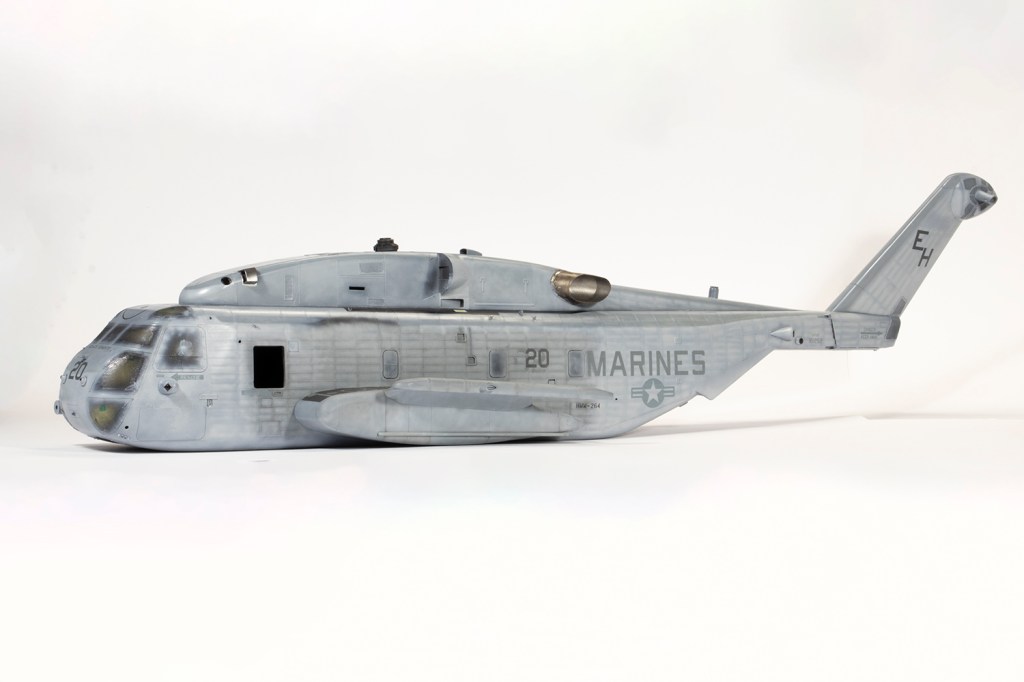


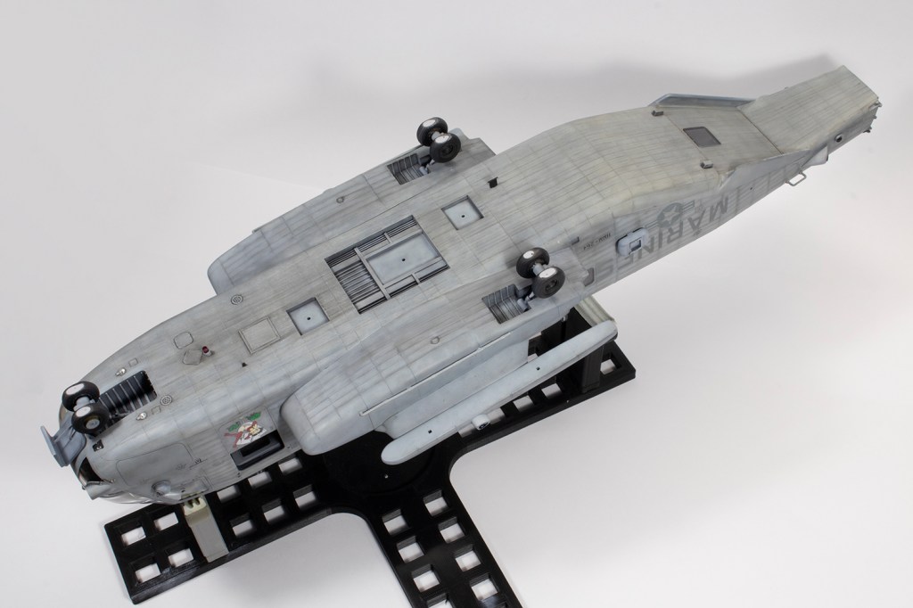


Weathering was a combination of variation in the paint and oils over the top – in general I used a mix of ABT502 Neutral Grey, Paynes Grey and Smoke as a filter over everything. This did darken the finish fairly substantially. Super Stallions could get filthy, but as usual I claim no accuracy, just something I found pleasing to my eye.
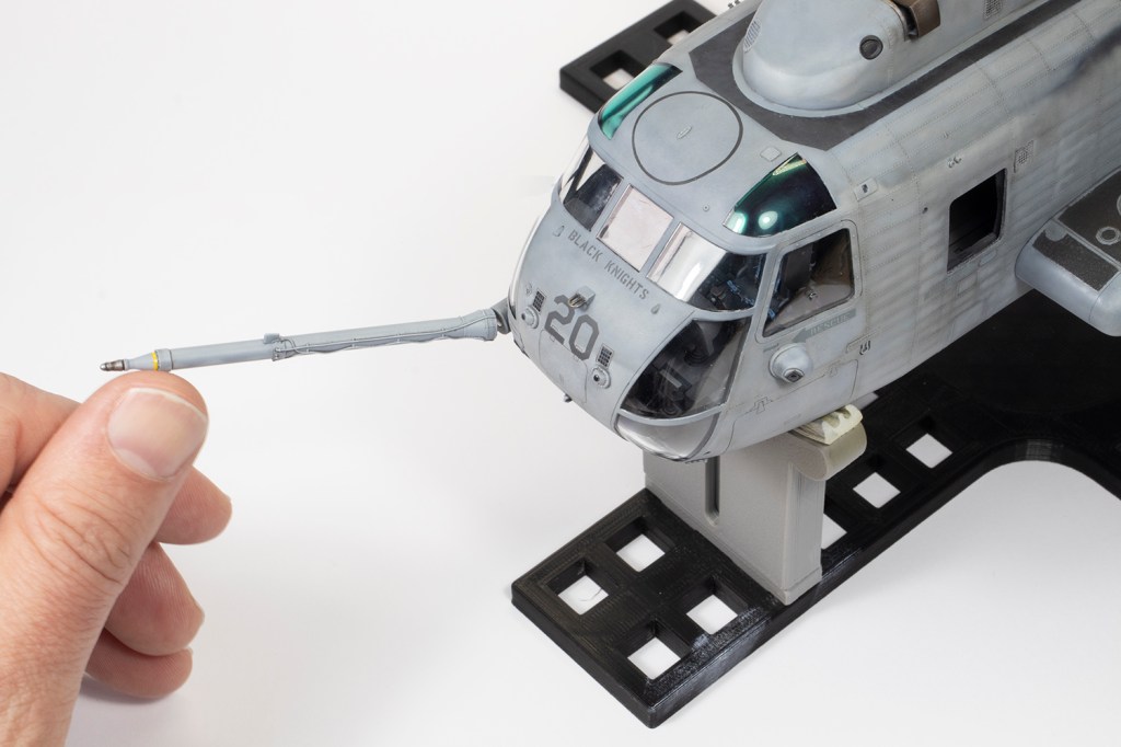
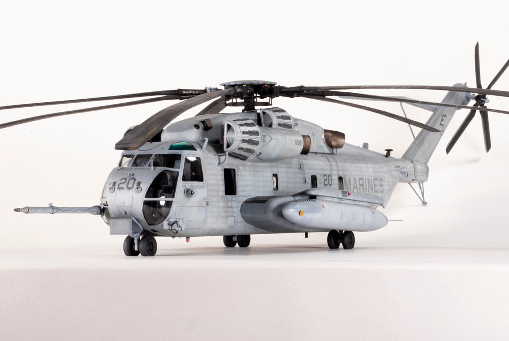
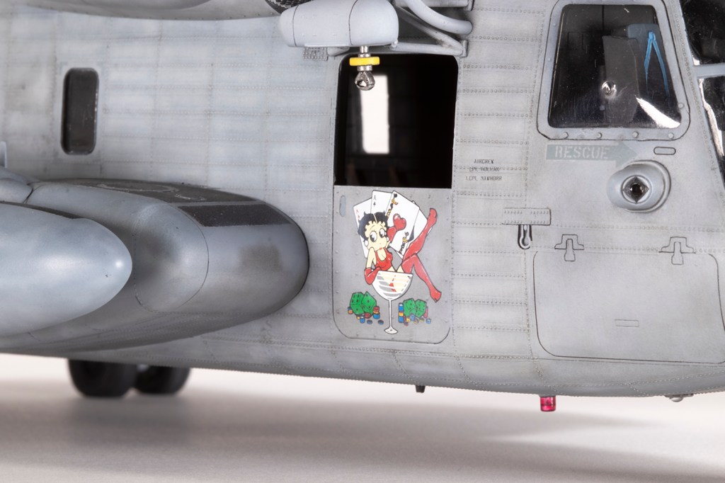
Adding all the little bits and pieces took a very long time, with detail painting as I went along and spot applications of VMS Flat to hide the glue spots. The refuelling probe caused me some anxiety as fitting it such that it would remain fitted was a challenge. A flash of inspiration caused me to try 2mm magnets. These were magic and allowed the probe to remain detachable. Cabling from the probe to the fuselage was added with 0.4mm lead wire, and cables from the NVG sensor arm and engine air intakes was replicated with 0.6mm lead wire. Again, you can really go to town with more wires around the engines, but I limited it to the more visible red cables.
The Eduard windscreen wipers are very delicate (more delicate than they should be) and were gingerly added and painted in place. Don’t worry about getting them symmetrical as they rarely were in reality, although I’m sure I’ll get dinged for this in a competition.
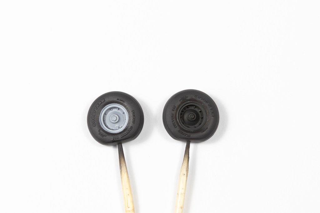
Fitting the landing gear legs was a dream; sadly not so with the wheels. These are by Armory and are fabulously detailed but don’t fit, which is somewhat bizarre as there’s no other kit on the market for them. You’ll have to butcher the beautiful brake detail to get them to fit over the kit axles. Not for the first time I found myself cursing aftermarket manufacturers for not testing their products.
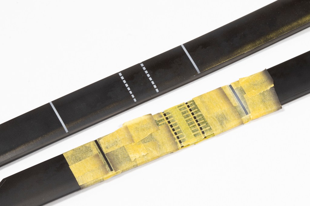
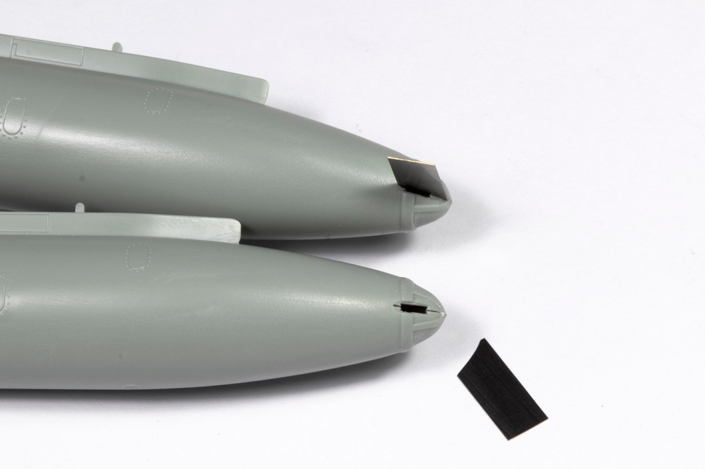
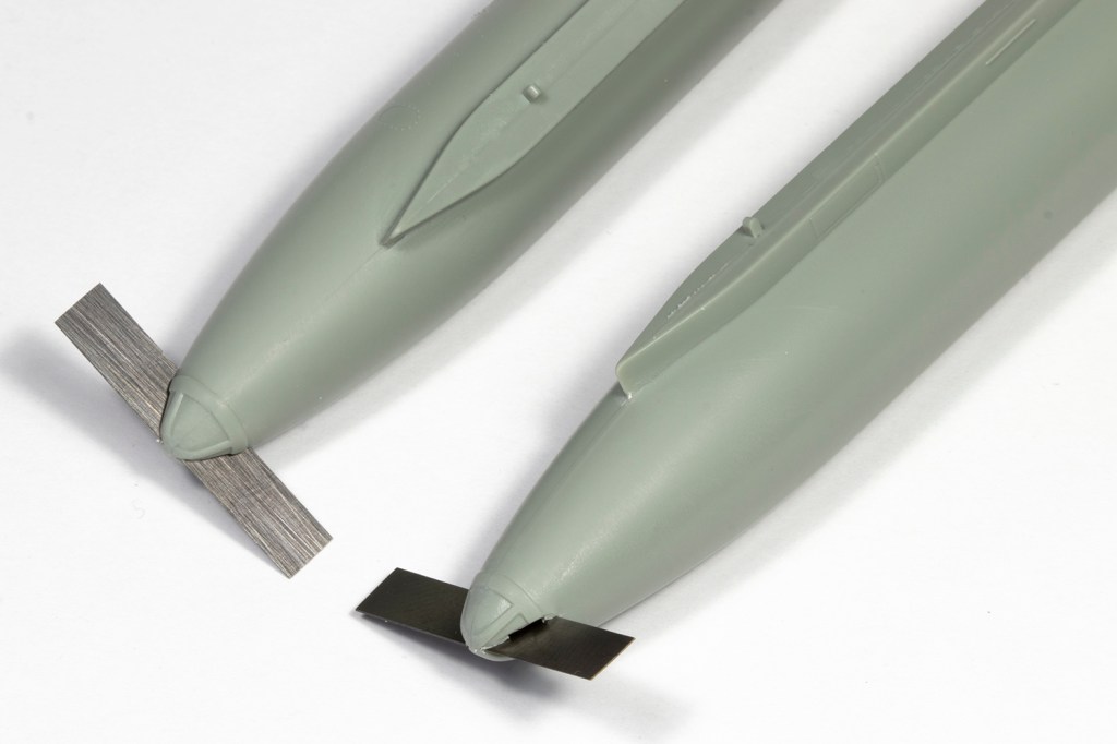
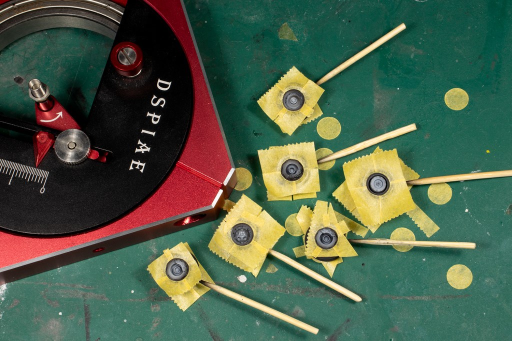
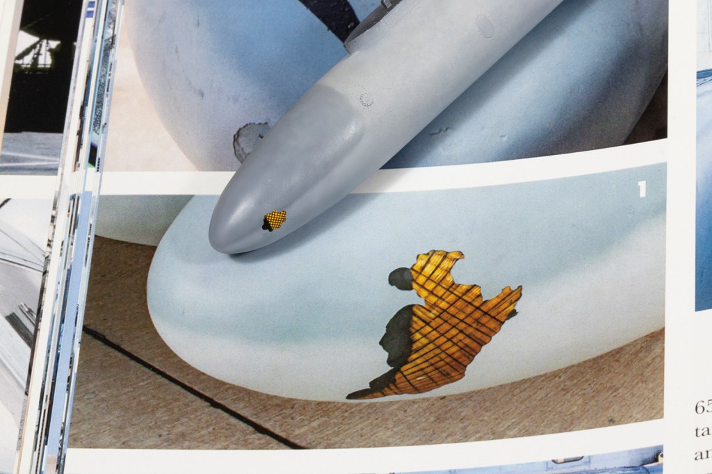
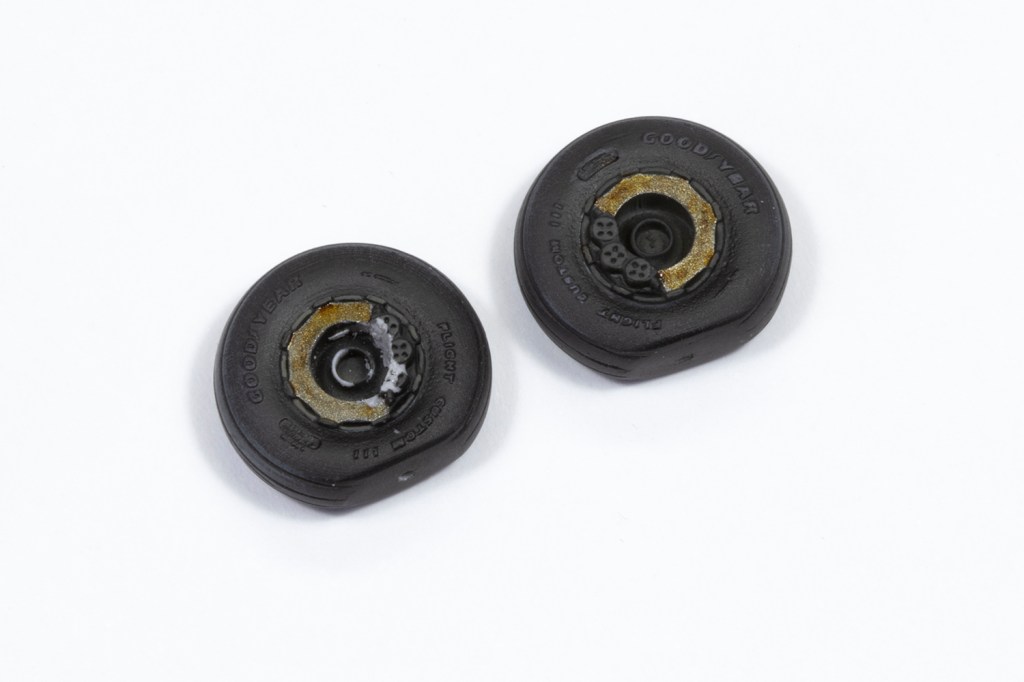
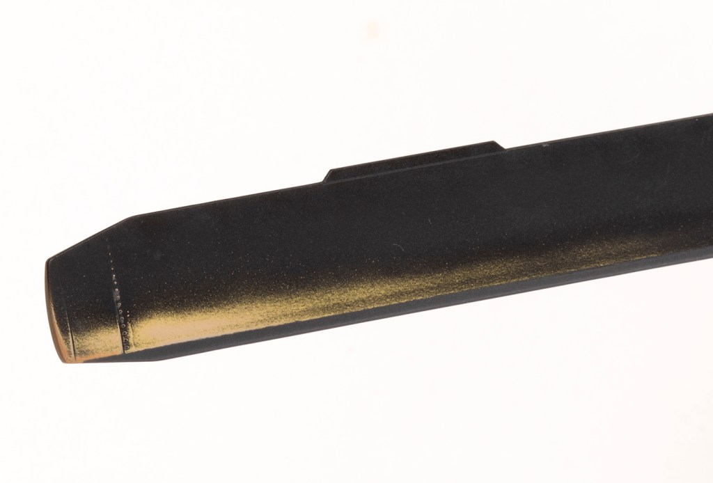
Rotor blades are tedious at the best of times; seven of them was borderline intolerable. The real things are made of fibreglass and resin and characteristically wear to a tan finish through the black paint and primer behind an anti-abrasion strip attached to the leading edge. I attempted to replicate this by painting black over yellow over tan and abrading it gently with 2500 grit sponge. It would have worked quite well had Academy moulded the blade profile smoothly. Unfortunately they put a dip just behind the leading edge, so the wear patter isn’t quite right. I also didn’t have the nerve to go too far, and in most places didn’t get to the tan layers. As such, my blades are too yellow. The rotor blade cuffs erode to a dull aluminium on the leading edge, and for this I used Alclad White Aluminium overcoated with MRP Super Flat Clear followed by Tamiya X-18 Black. X-20A can be used to wear the black away with a stiff brush to reveal the aluminium underneath.
In an effort to make this model somewhat transportable, I decided to magnetise the rotor blades to the hub. ResKit designed the actual hub so it could not be detachable, and thus the best solution seemed to be to make the individual blades removable. 2mm and 1mm magnets were used for this, and with some trial and error it worked well enough.
This is the most involved and complex project I’ve attempted since I started my current collection in 1994. It took five months, and therefore somewhere in excess of 150 hours of work. It could have taken so many more; many areas were neglected in detail and the overall effect is still quite basic. A good chunk of that time was spent dealing with inadequate aftermarket and adding all the rivets. The latter I do not begrudge, but the former is annoying. The air intakes are not worth the effort, and the rotor hub is so much less detailed than it should be. Combined with how poorly engineered they are, I cannot recommend them; likewise the wheels. The refuelling probe and tail rotor are decent additions, and the exhausts save a little time and seam work. I had fun painting the interior and adding all the belts, but it remains resolutely invisible on the finished model unless you’ve got a torch.
But, lest it sound like I’m whinging, this was a tremendous project that pushed my skills further than any other. I don’t have the energy to ever build another 1/48 H-53 (nor the space to store it!) but I’m exceedingly glad I build this one.


Year bought: 2007 (A model shop, Zhengzhou, China)
Year built: 2024 (New Addington, Croydon)
Back to home.
