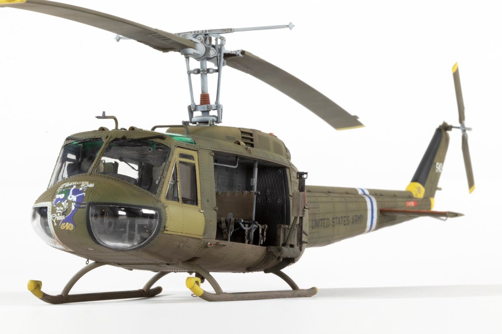
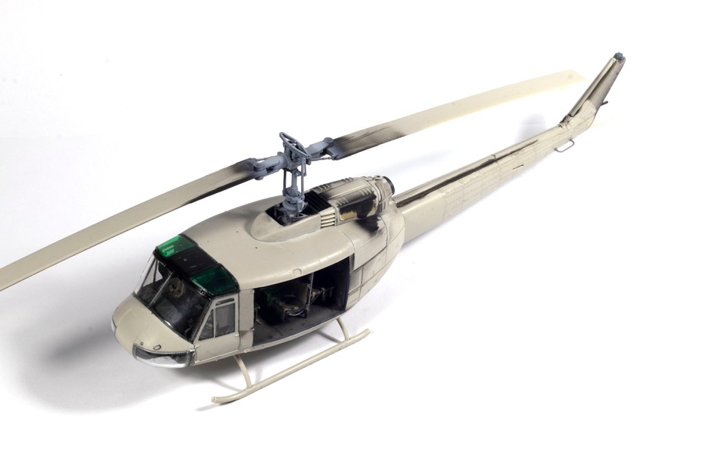
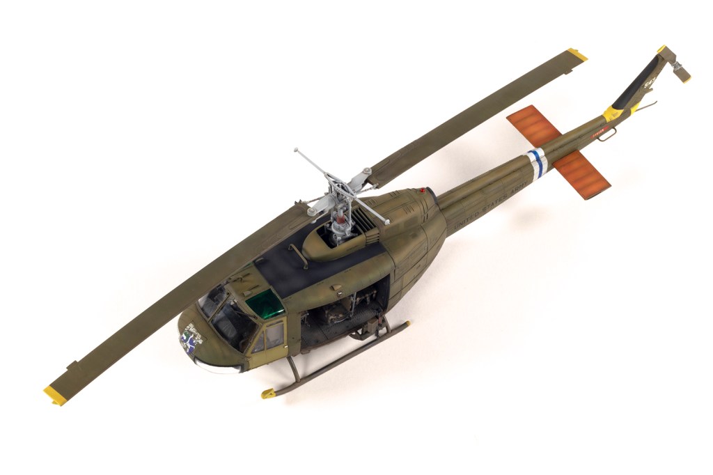
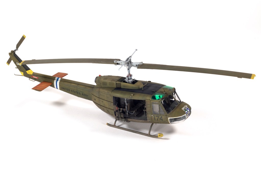
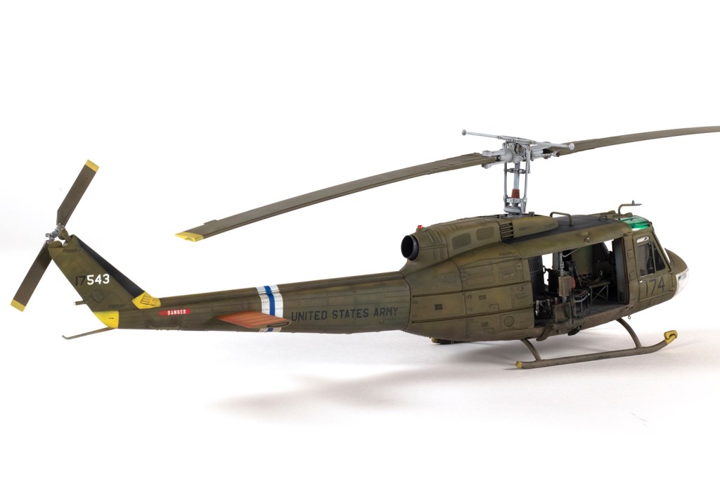
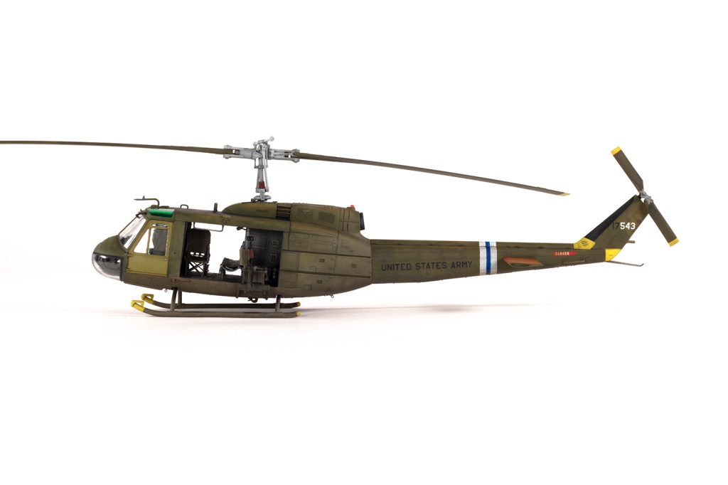
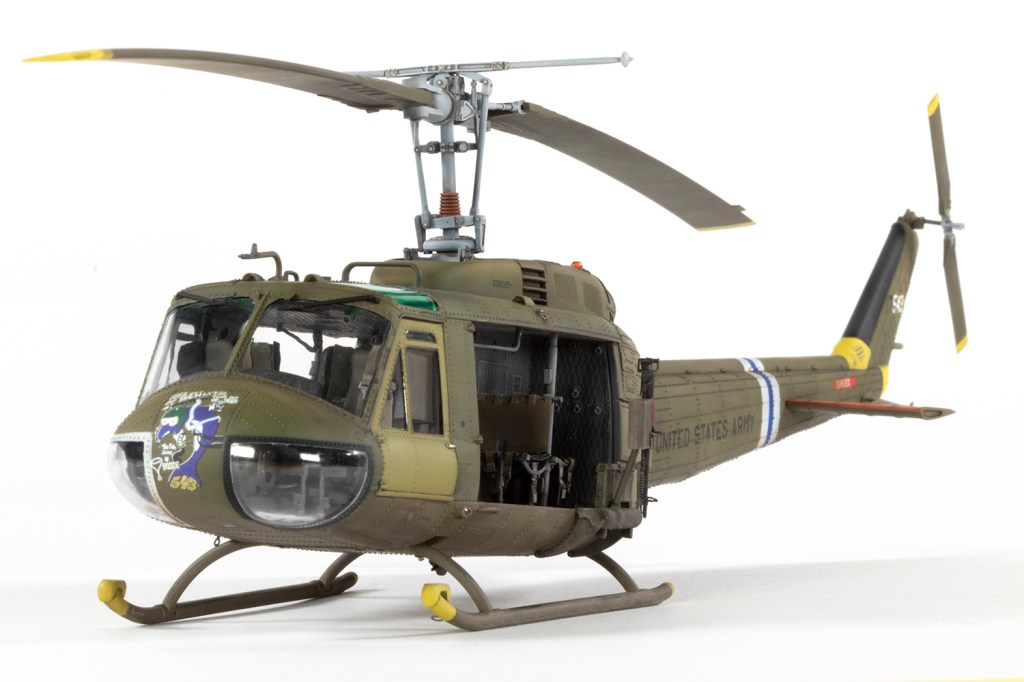
with ResKit resin interior, rotor mast, tail rotor, guns, exhaust and Werner’s Wings decals
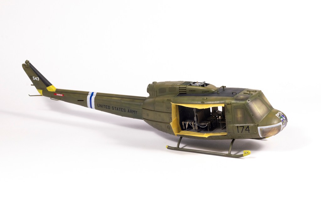
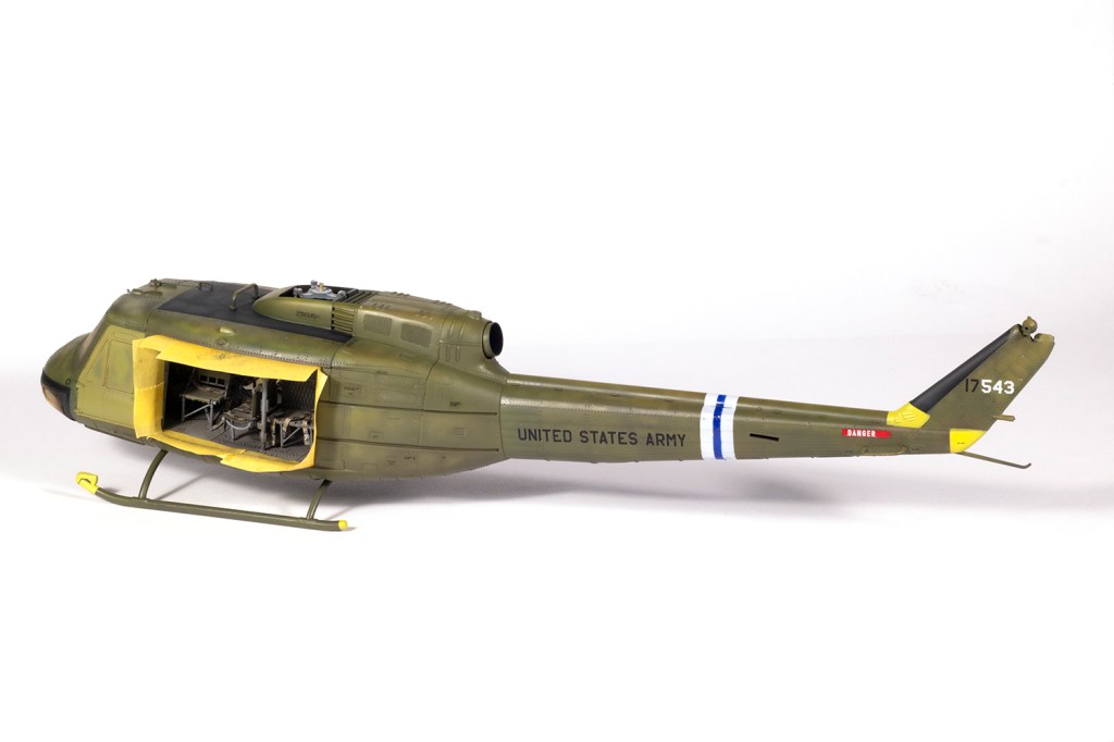
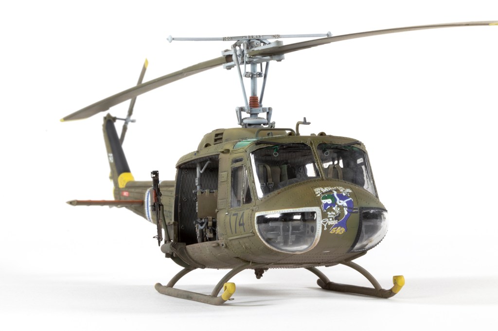
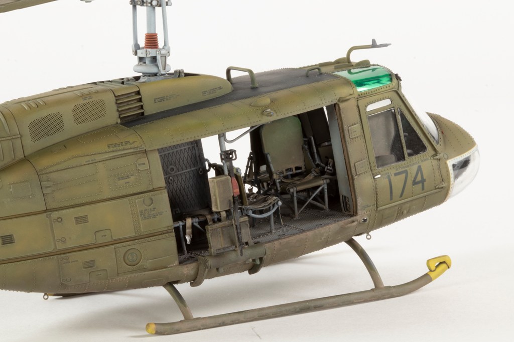
174th Assault Helicopter Company, US Army, Vietnam 1968
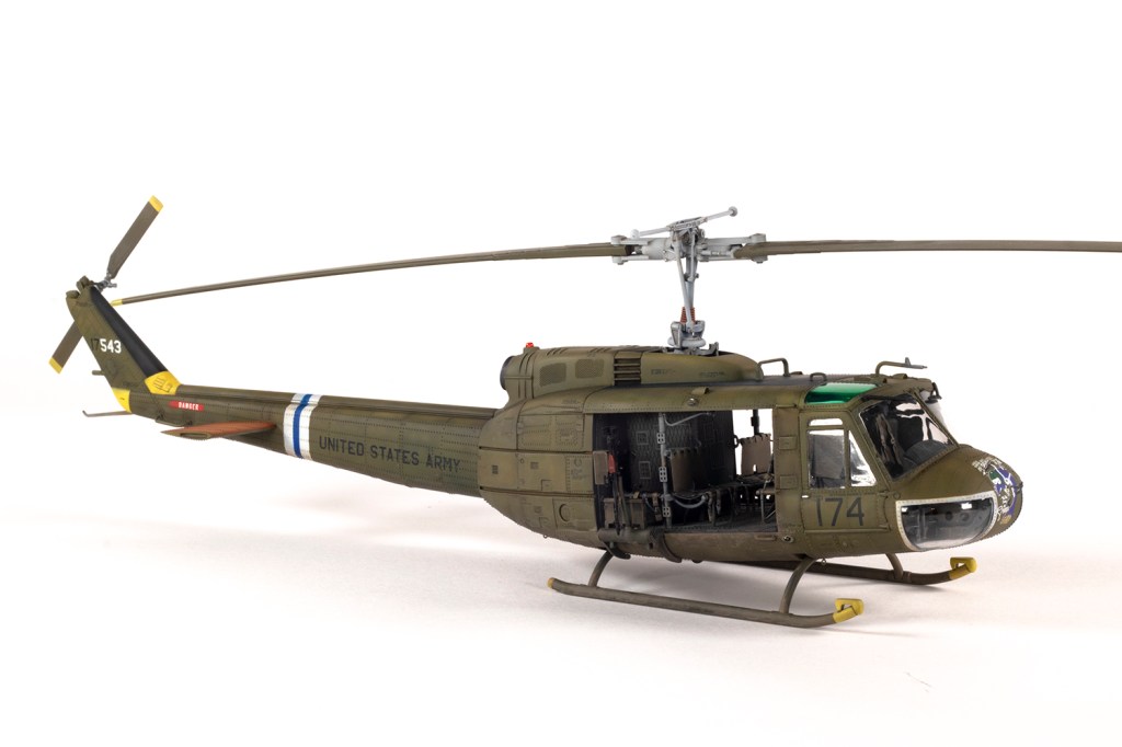
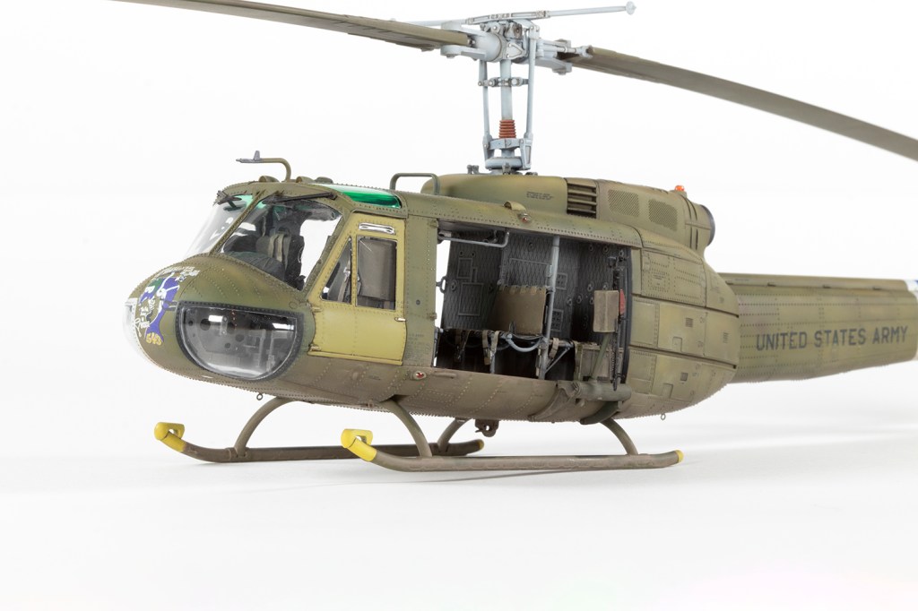
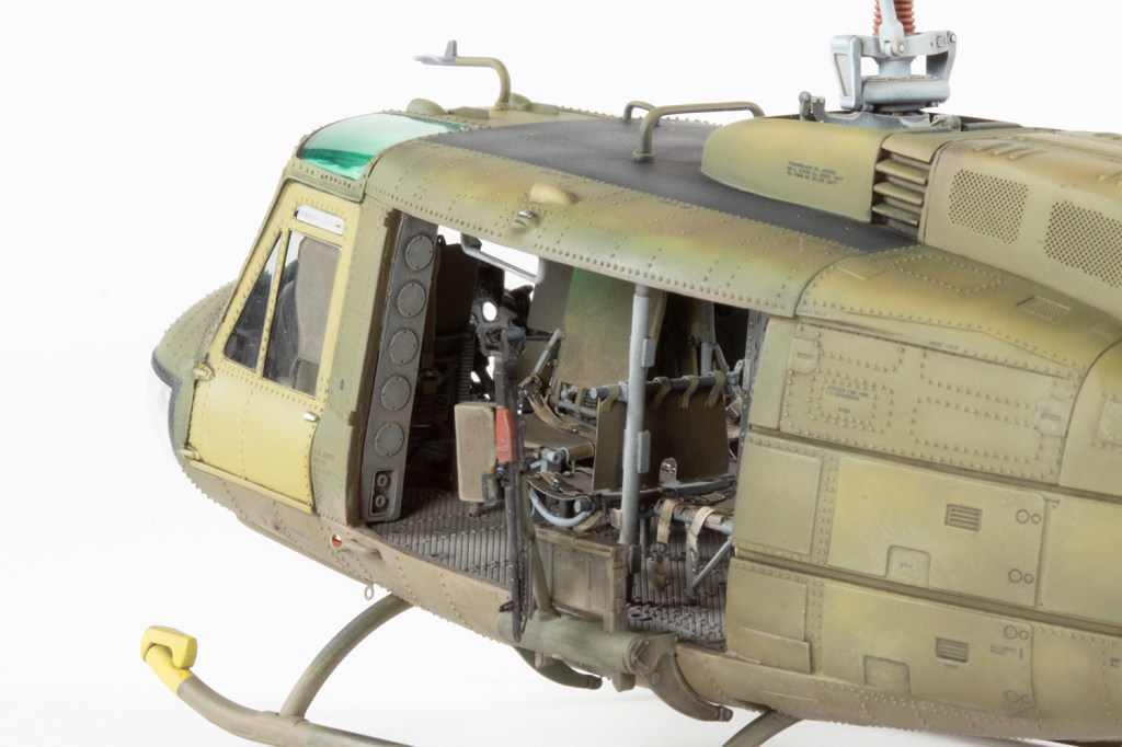
I’m sure I’ve remarked before that some projects just produce a natural focus point for the model. This is one such model. It’s all about the aftermarket interior and rivets. Lots of rivets.
Helicopter modellers rejoiced in 2017 when Kitty Hawk released a new tool UH-1D in 1/48. Kitty Hawk are (were?) a company with a mixed reputation at best, but this kit was considered a Good One. Accuracy and fit are generally fine and the detail is excellent.
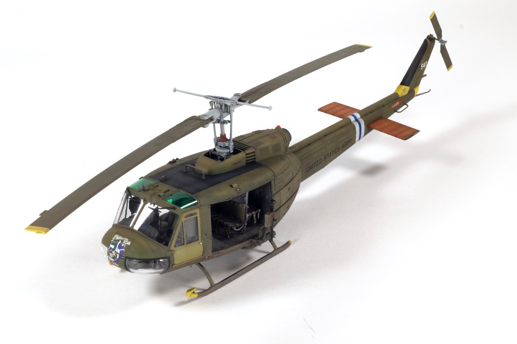
There are tons of markings provided in the box, for several Vietnam airframes as well as later Hueys from Japan, Germany and Taiwan. Although marketed as a UH-1D, in reality the kit’s schemes are for a mix of D and H variants; the latter differed by engine type and had no nose pitot or antenna. As such, you need to have your wits about you to make sure you use all the correct parts since the instructions offer no guidance at all.
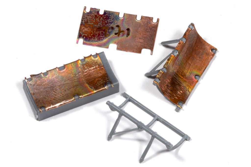
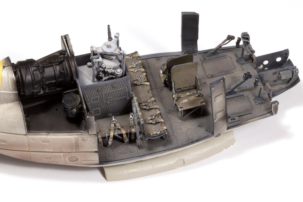
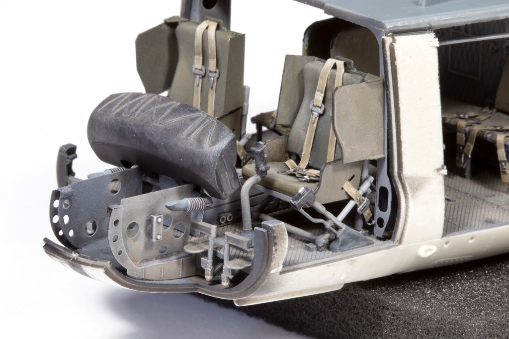
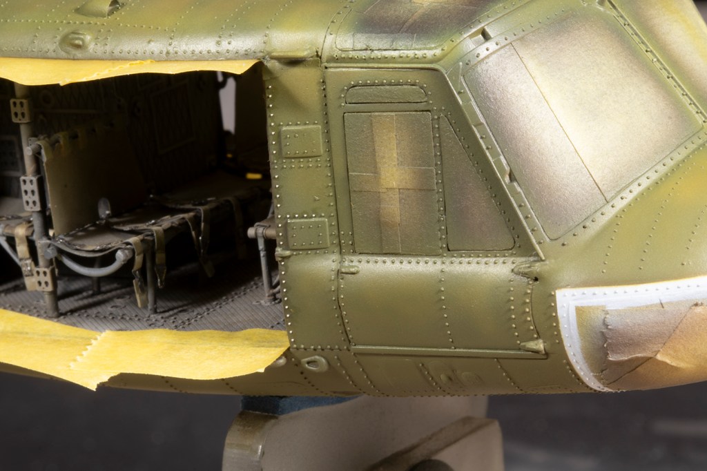
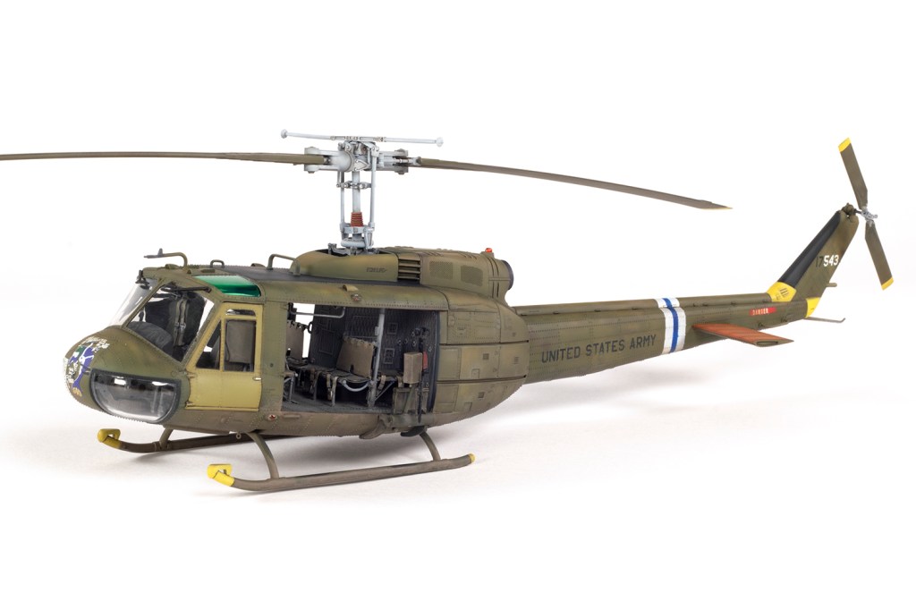
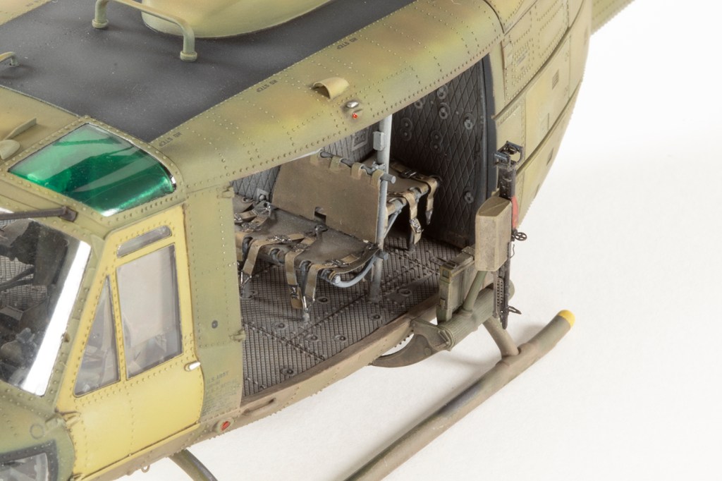
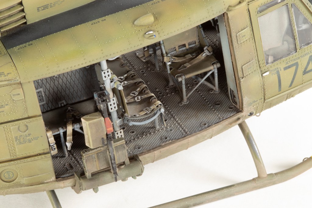
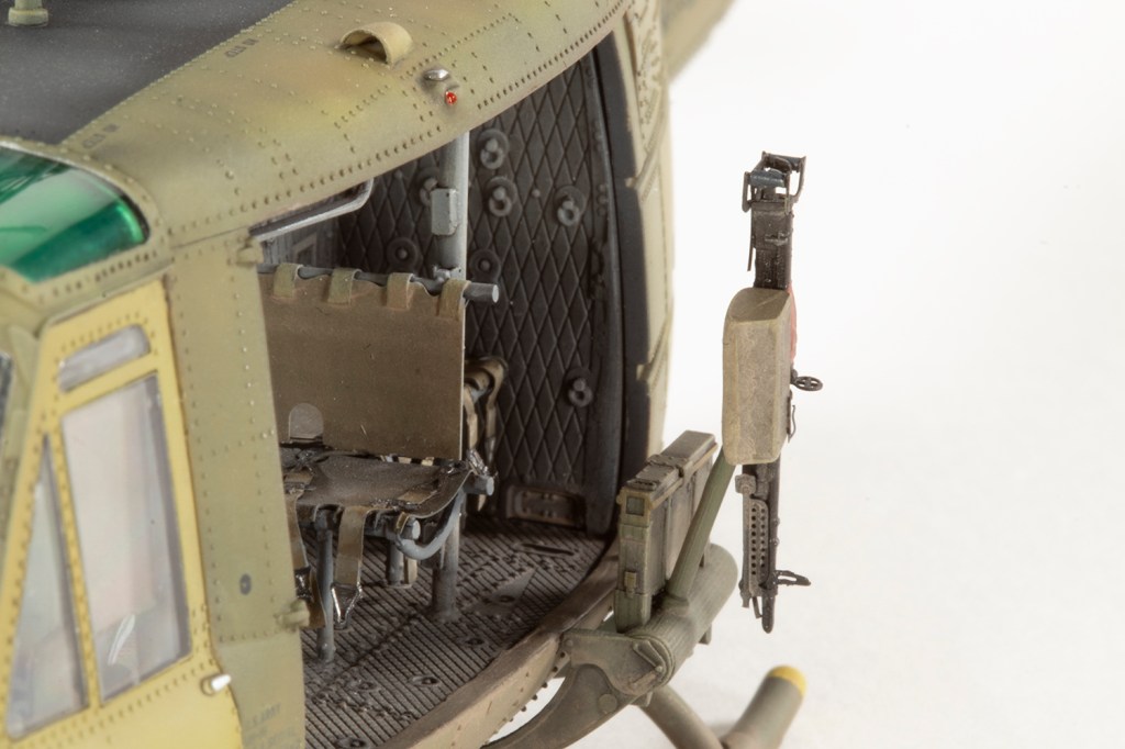
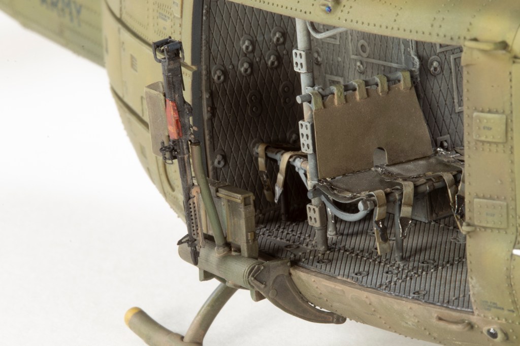
I acquired this kit in 2018 and over the intervening years obtained as much ResKit aftermarket as I could, more through accident than by design as one always needs to ask for something at Christmas and birthdays. This included resin guns, exhaust, tail rotor and main rotor, but the real highlight was the full interior set, which comprises a ton of resin parts cast from 3D printed masters and a couple of sheets of PE.
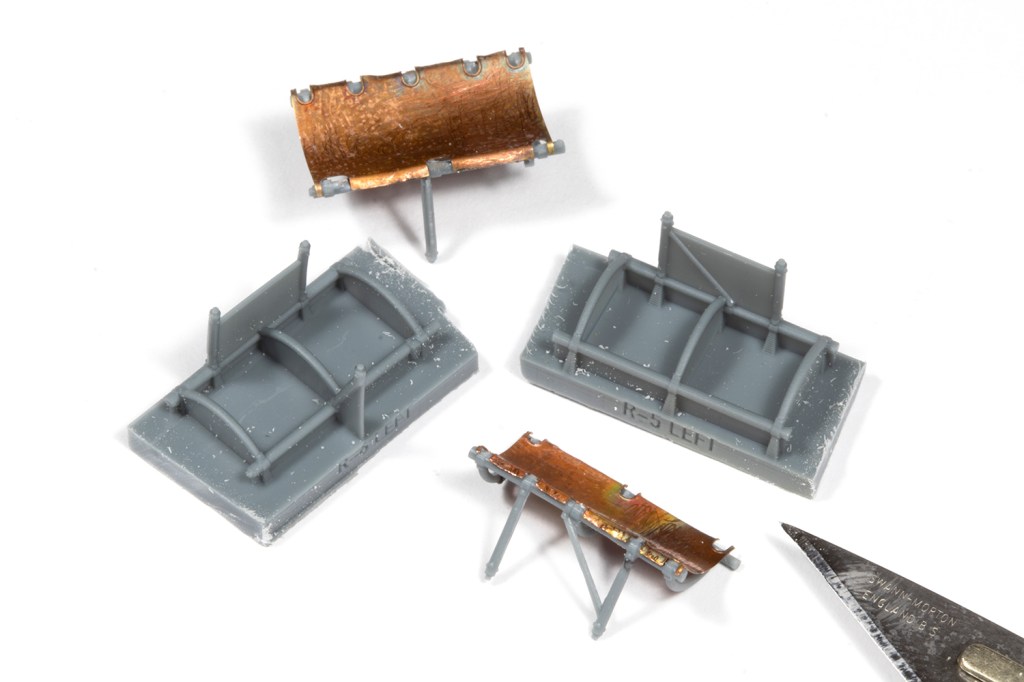
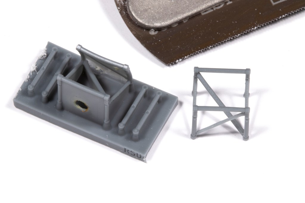
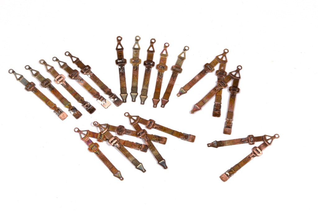
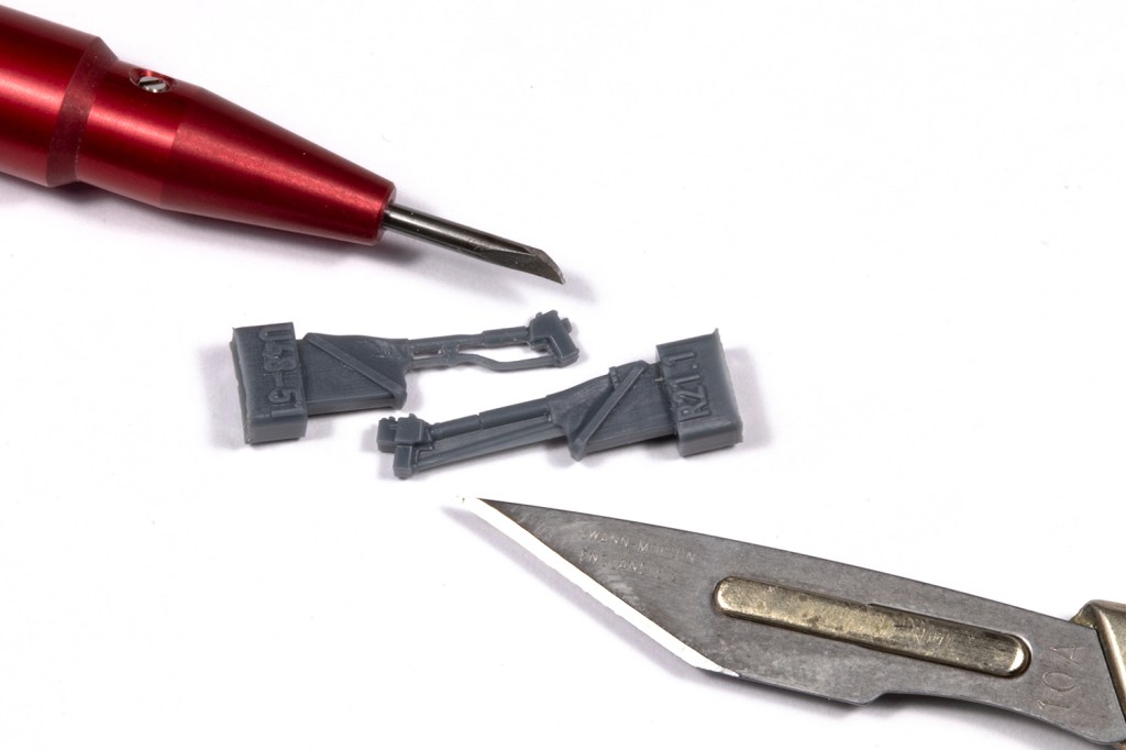
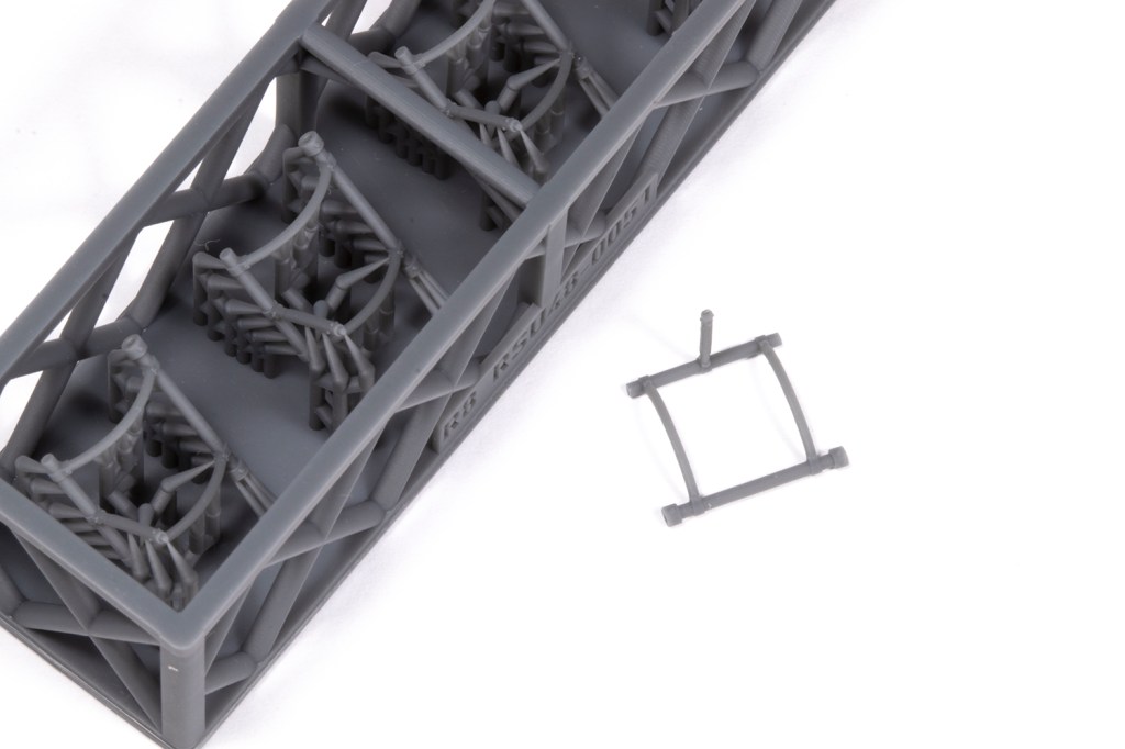
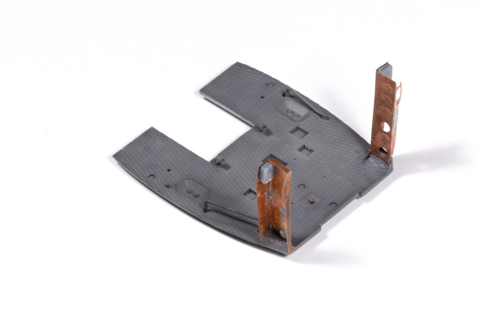
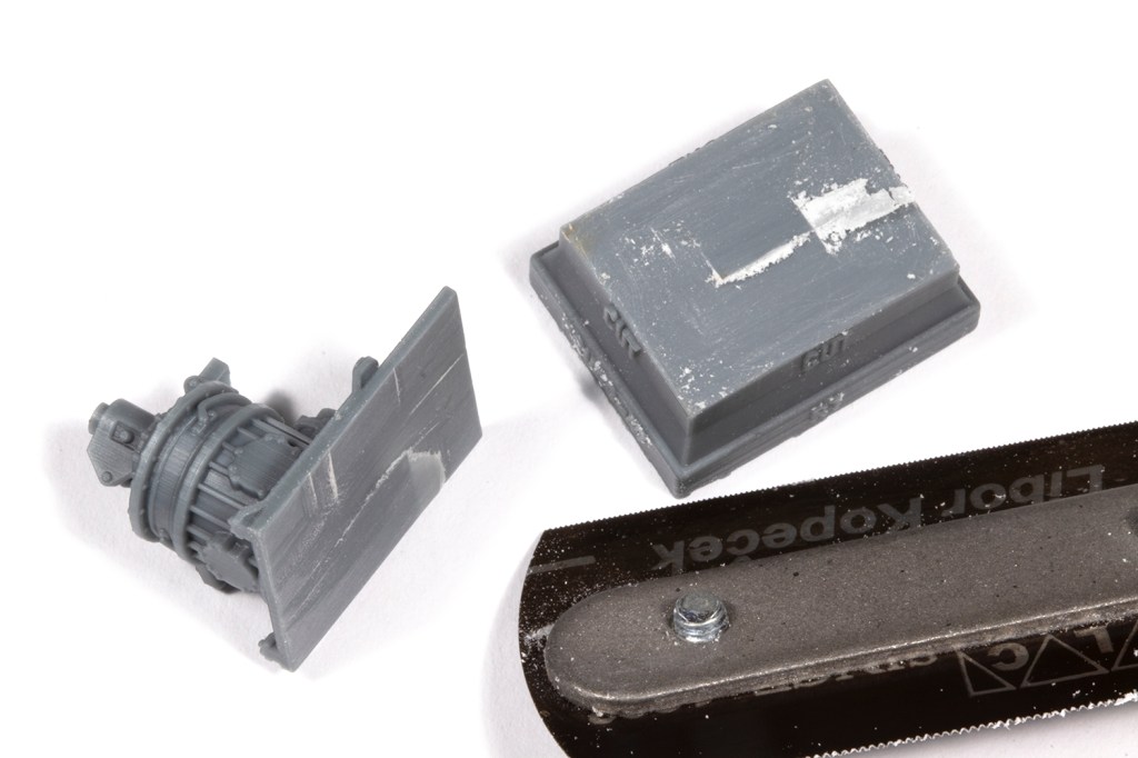
This interior is really aftermarket to put hairs on one’s chest, and I am immensely thankful to YouTuber Hammerhead Models for his video on using this set. Had I not watched it, I would not have been forewarned, and if you have this set, you definitely need to be forewarned. In many ways it is an excellent product, but it was produced pre-Covid with (in ResKit’s words) the best technology they had at the time, and things have moved on a lot since then. The main challenge is releasing a lot of extremely fragile and fine parts from some very substantial moulding blocks with extensive moulding flash, and this requires creativity and forethought. I used a wide variety of tools – razor saws, a variety of scribers, new scalpel blades of different shapes, drills – to take a very long time to remove each part. I started with the hardest components, which were the ultra-fine seat frames, on the basis that if I couldn’t get these done, I’d abandon the seats altogether. Light pressure and many, many passes were necessary.
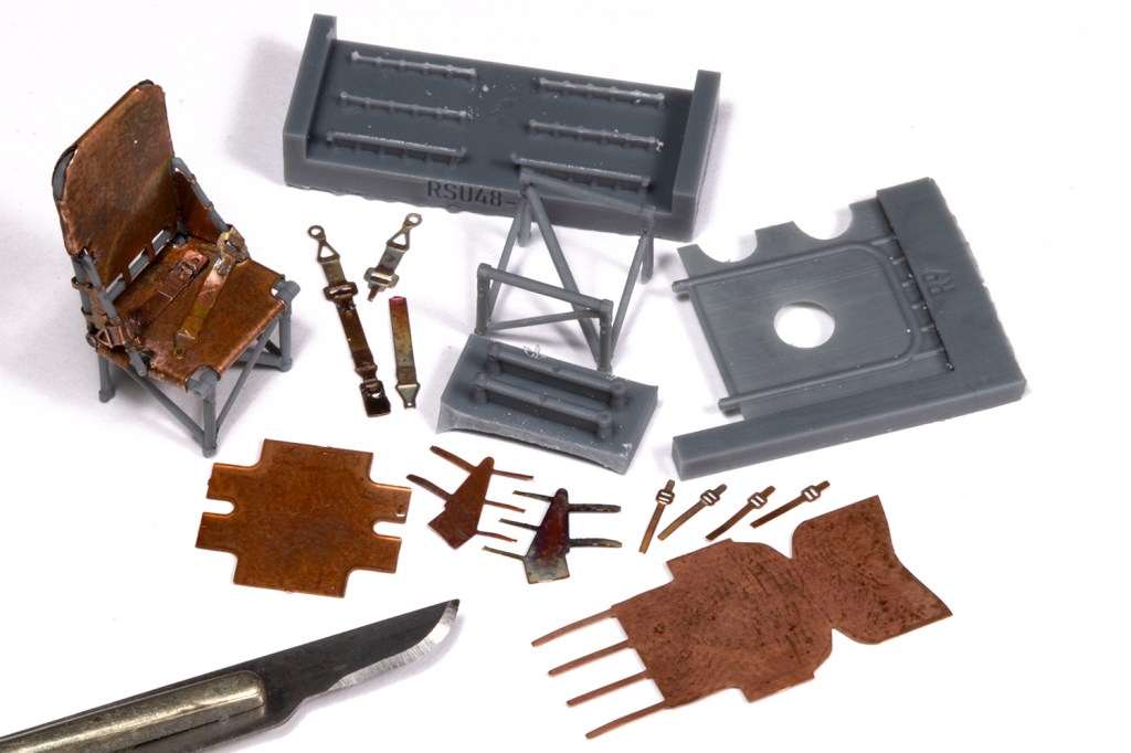
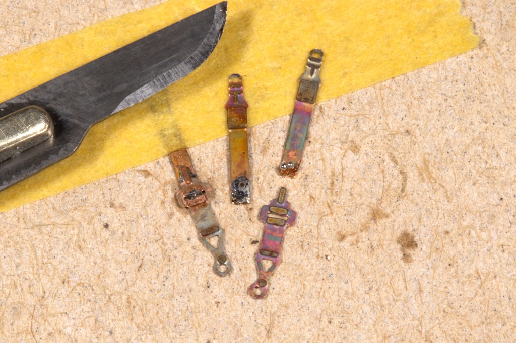
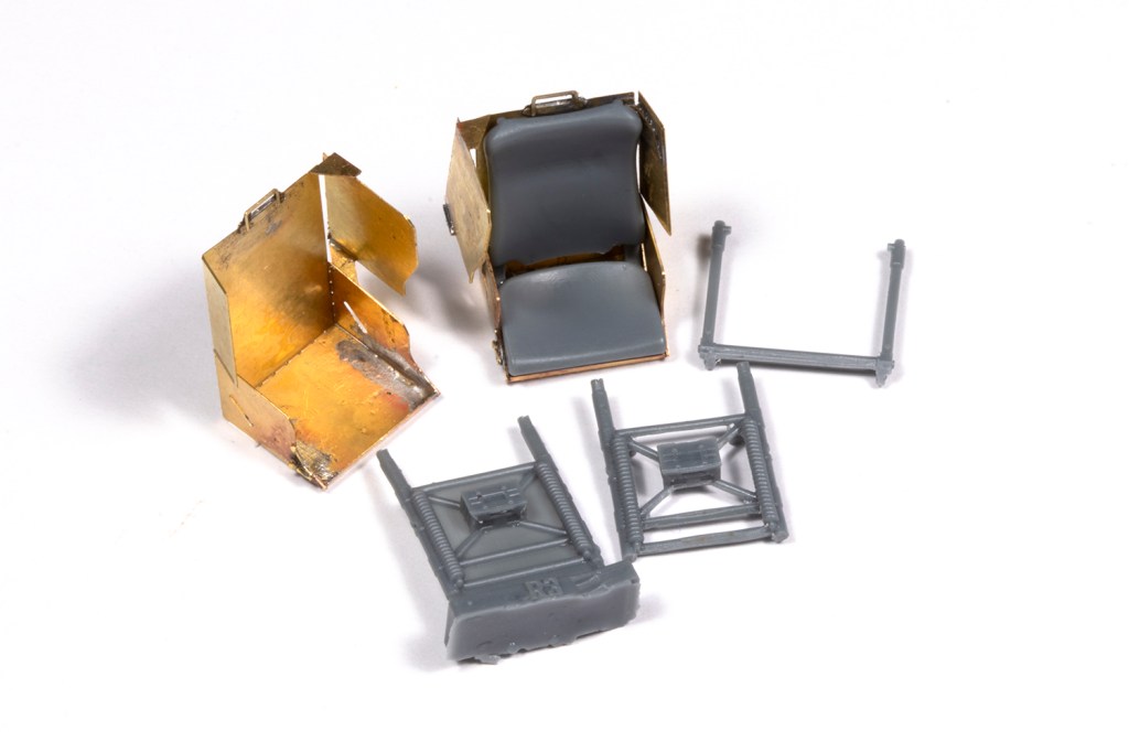
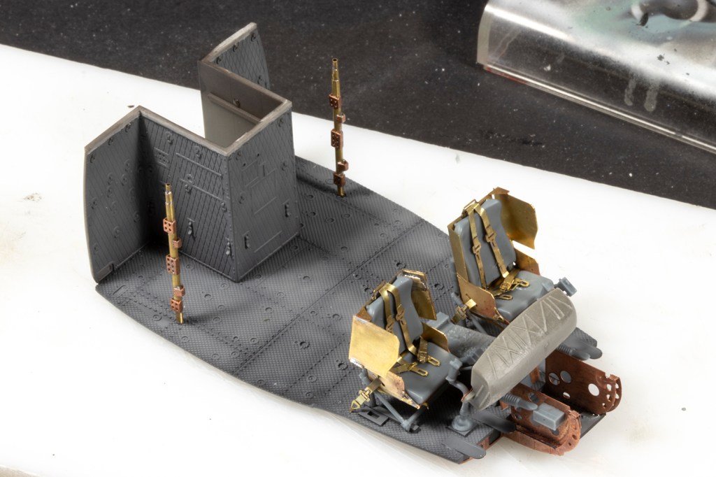
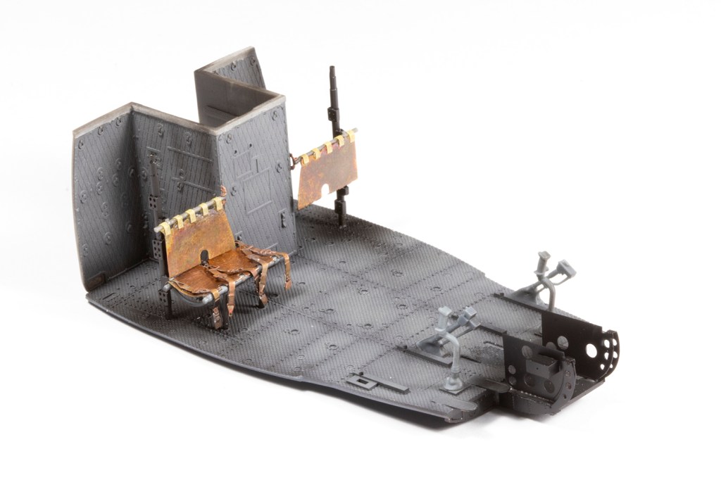
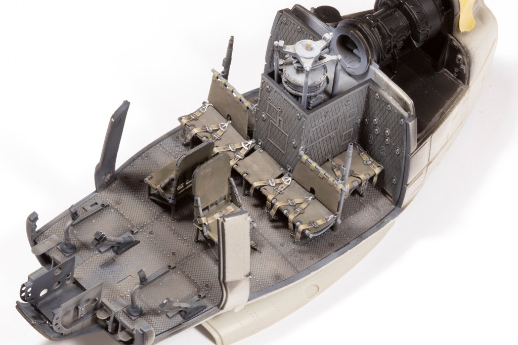
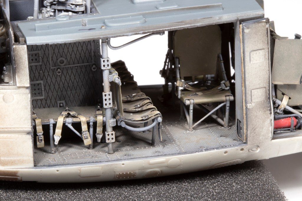
Over several days I slowly released each part, and each part released was a satisfying victory. Most of the frames did get broken somewhere, but in a manner easily fixed with a dab of superglue. With a complete set of frames, I could anneal the brass ‘fabric’ seats with a lighter and mould them over the resin buck supplied by ResKit. There is a small mountain of seat belts to make, and as for most of the PE components, I elected to solder the parts together where I could.
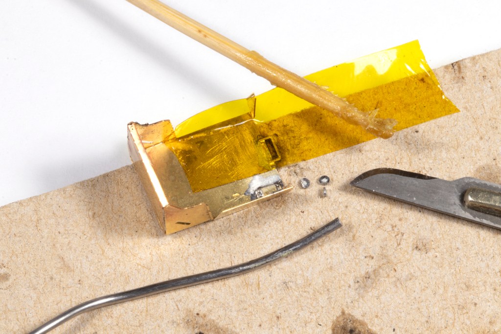
I love soldering PE, partly for the challenge and satisfaction, and partly for the strength of the bond. I use a cheap soldering iron from Amazon and tape the PE parts to a jeweller’s soldering mat with Kapton tape, which is heat resistant. This fixes the parts in place and allows me to use tiny fragments of solder cut from a reel and tacked in place with Nokorode Soldering Flux Paste.
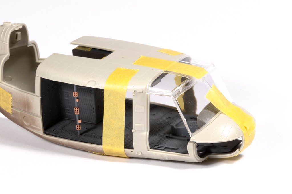
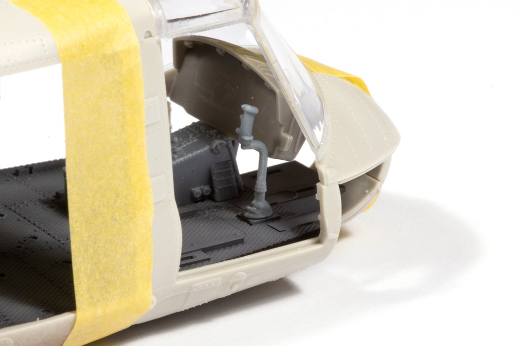
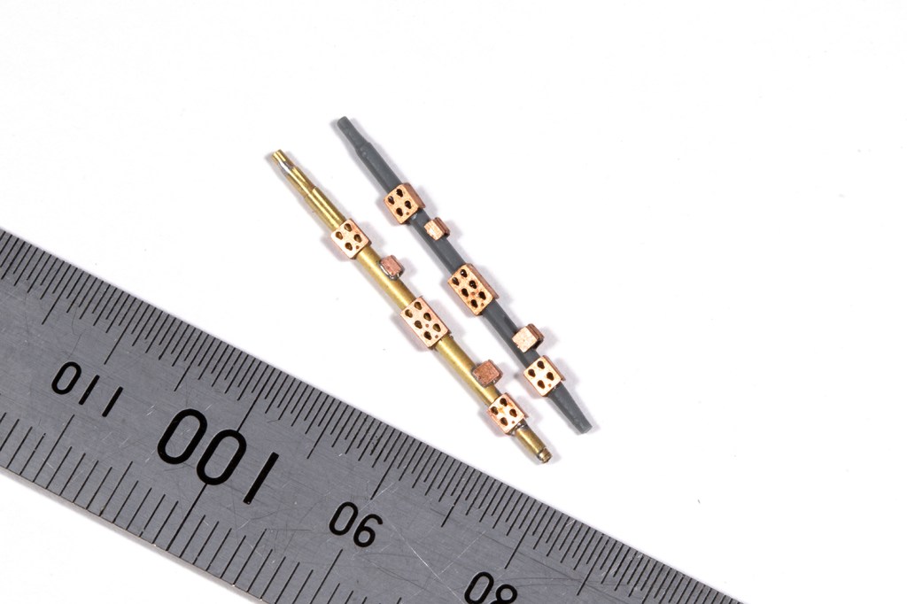
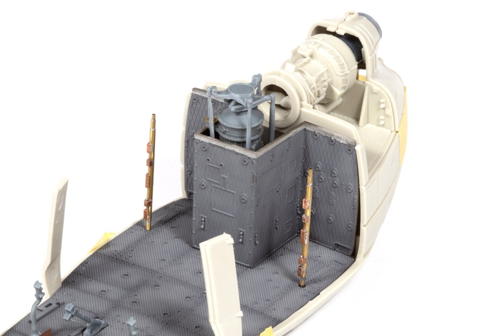
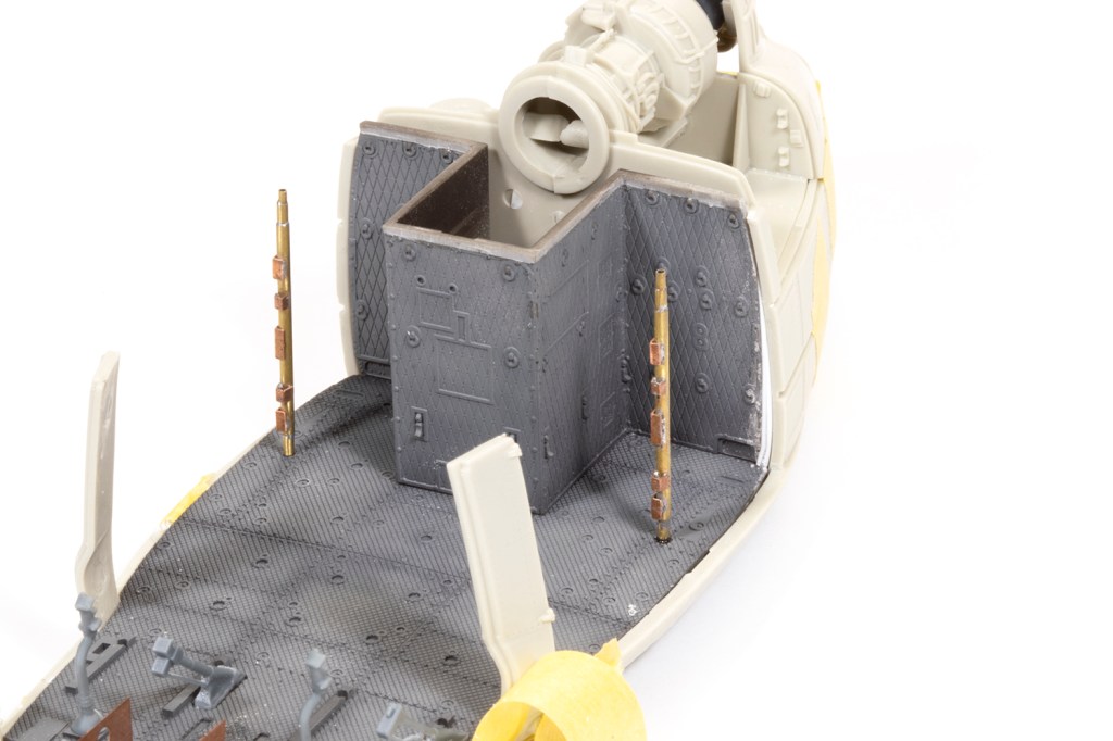
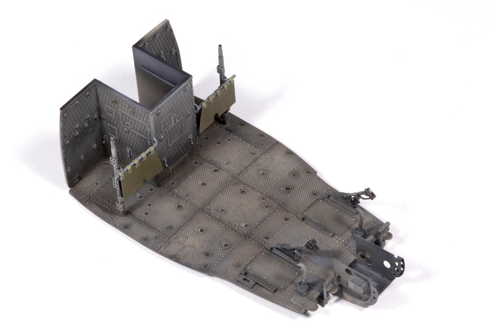
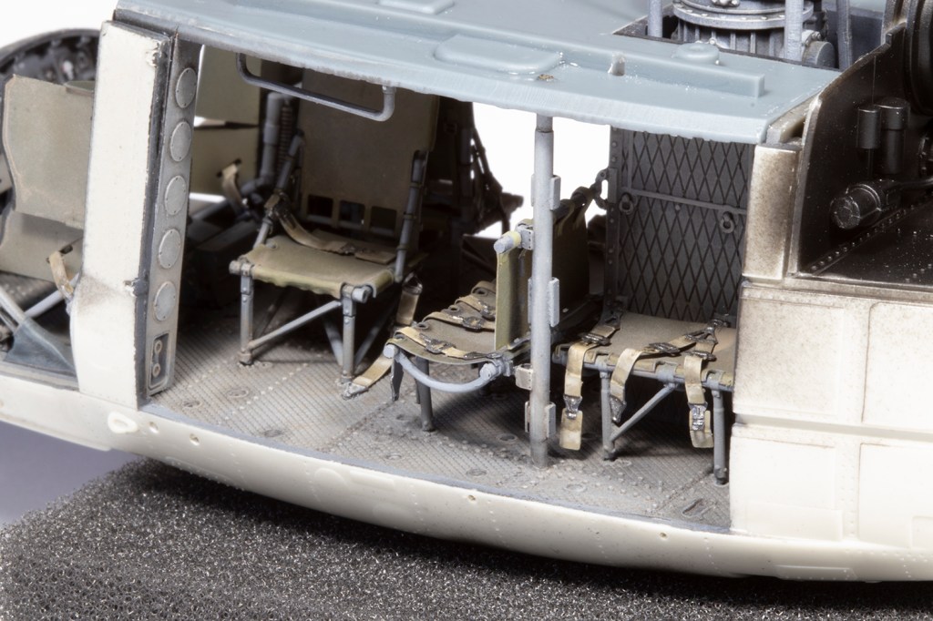
Hammerhead’s video warned me that test-fitting all the interior components was essential every step of the way. The resin floor, rear bulkhead and roof fit together fairly intuitively, but there are a couple of resin stanchions to also fit and some PE pillars, which look terrifying. One of the stanchions snapped during a test fit, and I decided to just replace them with brass tubing and soldered the PE fittings to them. This was a good decision as it made for a much more robust assembly.
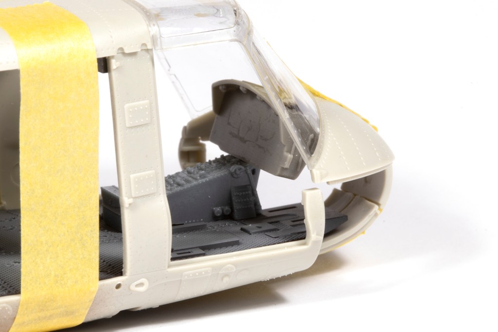
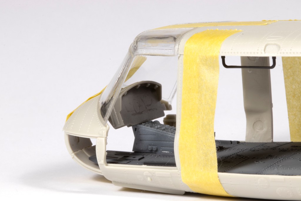
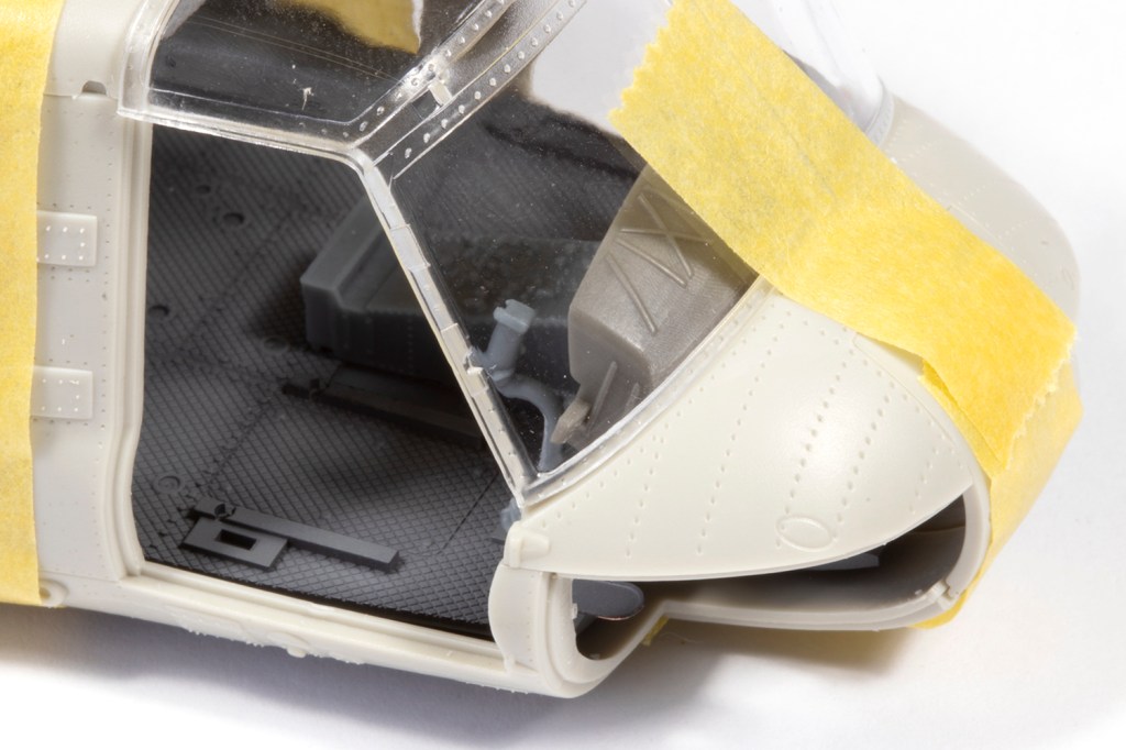
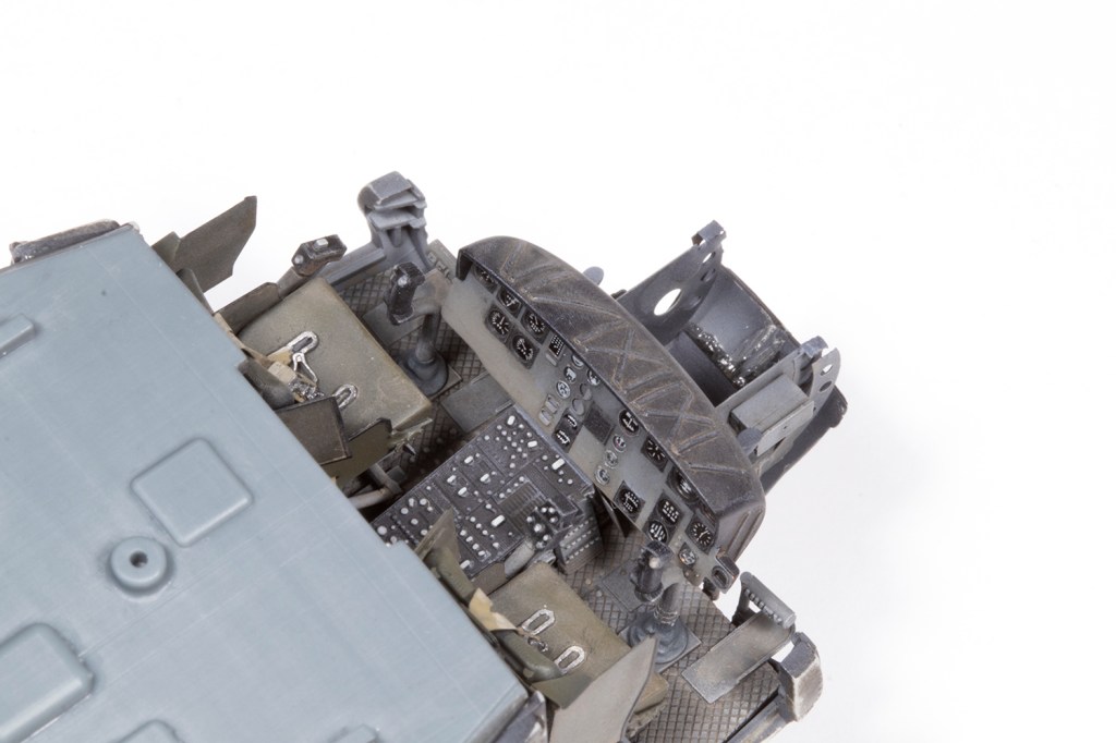
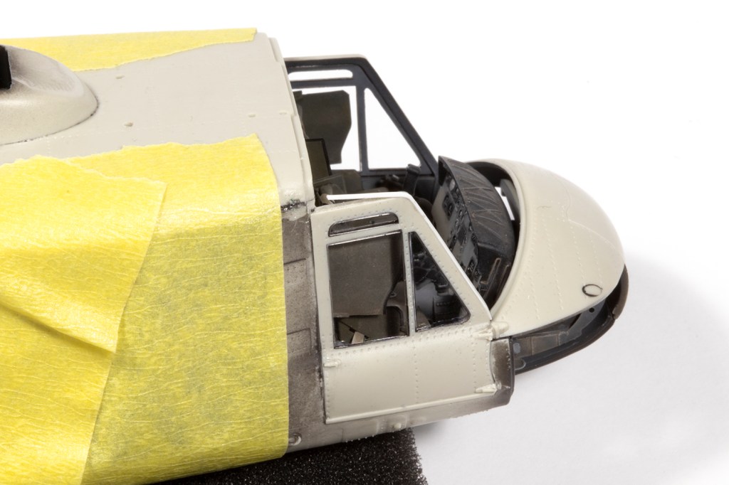
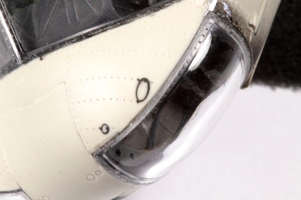
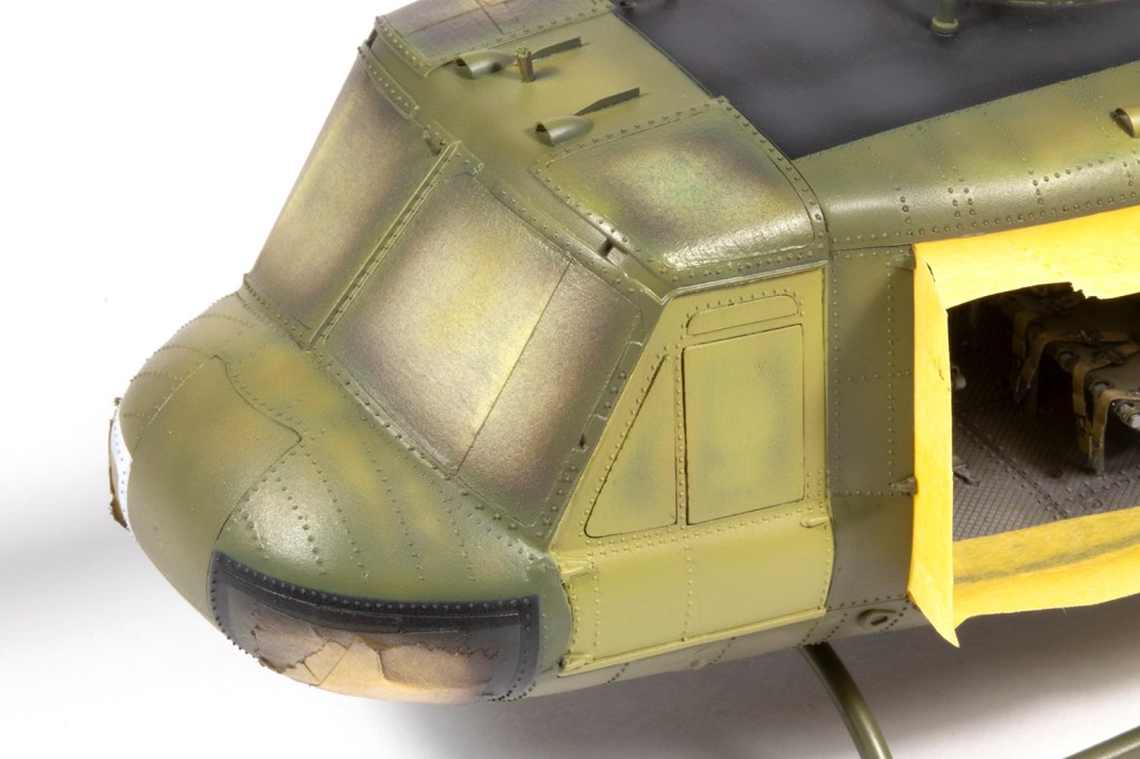
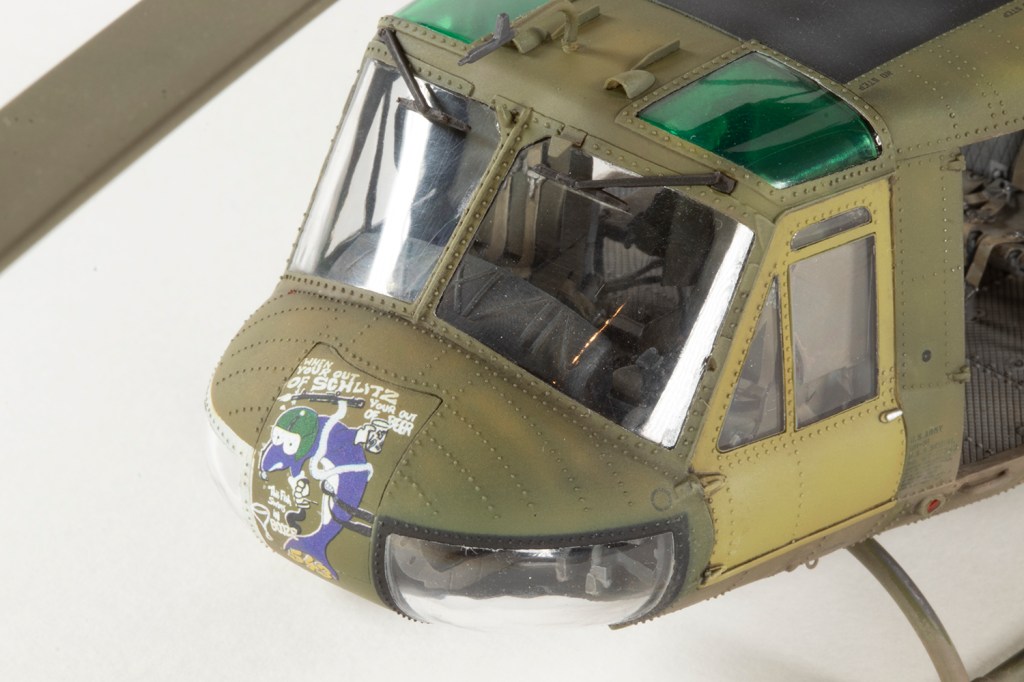
The biggest anticipated problem was getting the instrument panel coaming to not foul the windscreen and upper nose. I suspect this might be a problem even if you use the kit part, and I did lots of test fits to ensure everything would join up as it should. I found the easiest solution was a combination of moving the entire centre console aft by about 2mm (which is as far as it will go before interfering with the cyclics) and removing material from the back of the coaming. The forward fuselage assembly is fairly complex, with the front doors, windscreen, upper nose, fuselage and nose windows all having to come together in just the right way. Eventually I managed it.
At some point along the way I lost the rear centre seat frame. One day I had it, and the next I didn’t and in desperation I emailed ResKit to ask if they had any spares lying around. It turned out they didn’t, but remarkably one of the designers messaged me to say they had dragged out the old CAD and would print me a replacement. A couple of weeks later, several of these parts arrived – now that’s customer service! The printed part was much finer and easier to use than the original cast parts, enough that if ResKit ever re-released this set in 3D printed form, I would consider buying it and doing a UH-1D.
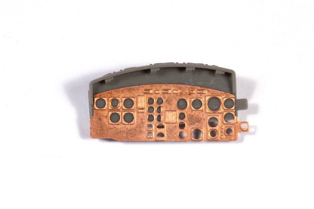
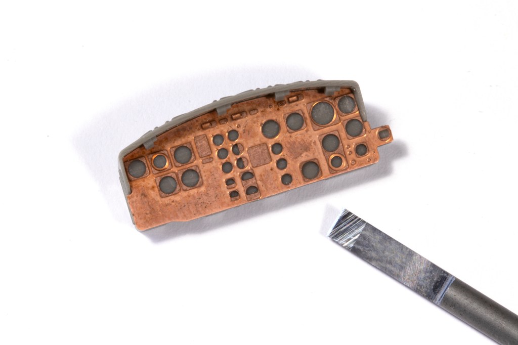
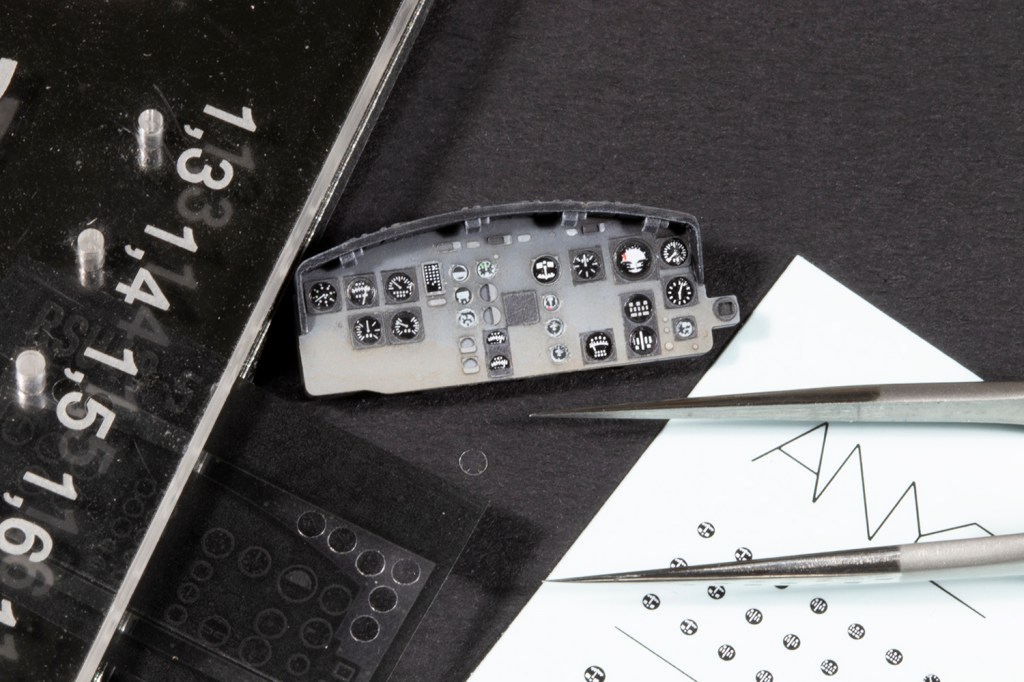
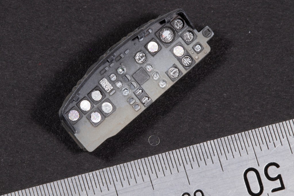
I couldn’t get the PE instrument panel to fit in the resin coaming, so some thinning of the resin lip was required. I also decided not to use the supplied acetate film dials, but rather apply some dial decals from ANYZ and Airscale once the panel was painted. After these had been covered with discs punched from clear acetate, I rather liked the final effect.
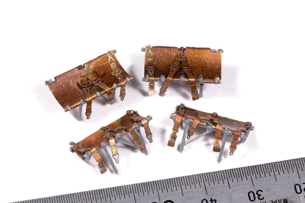
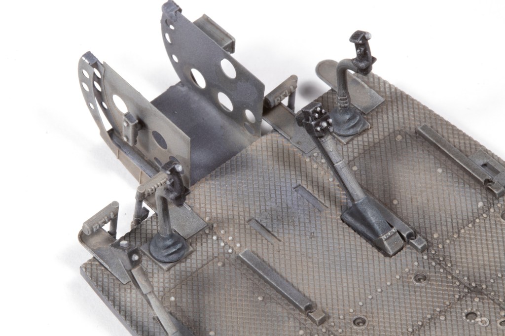
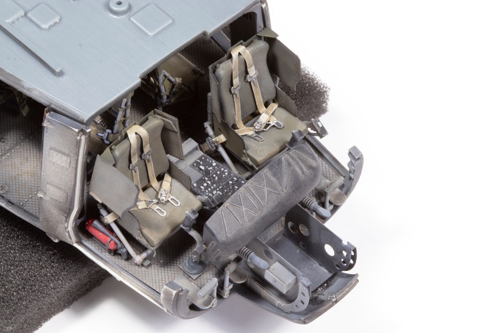
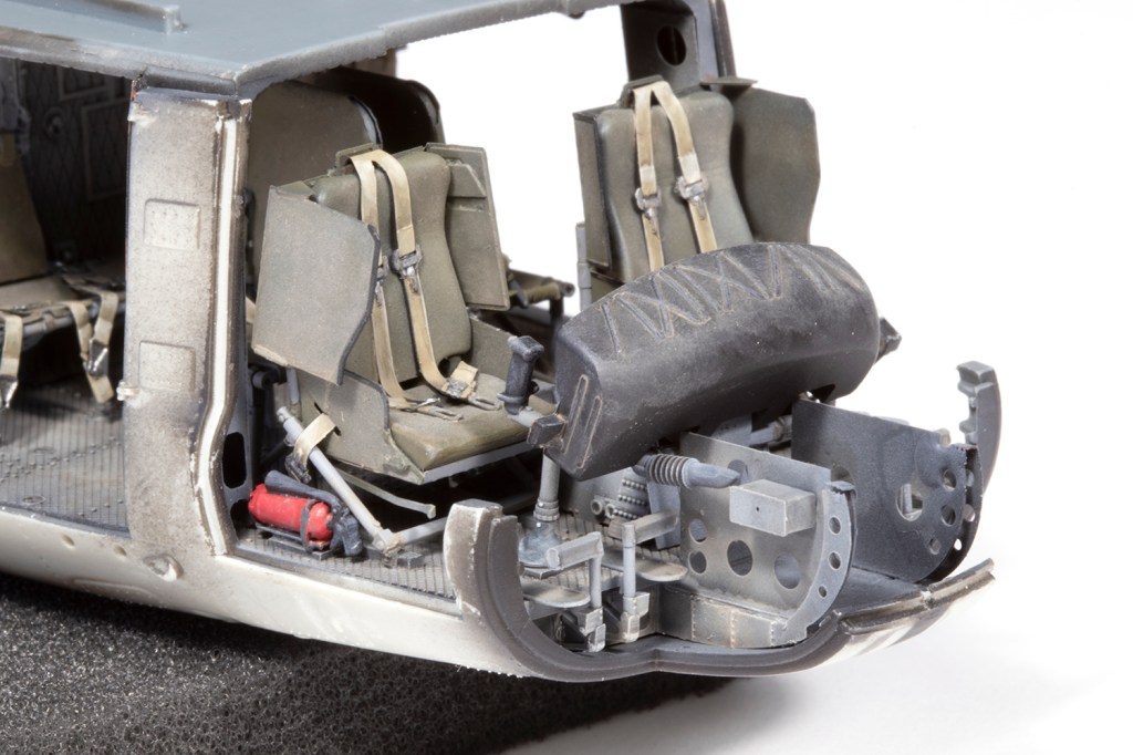
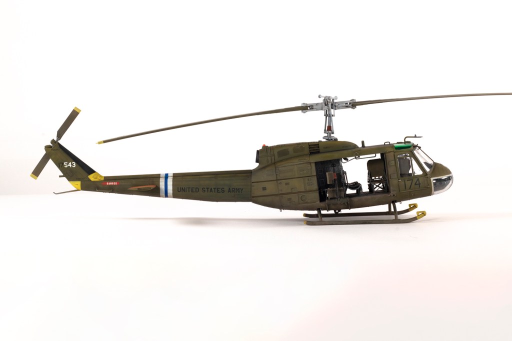
The interior is incredibly complex, and the centre cabin seats and pilot seats were the most complex assemblies of all. I confess that I did not use all of the tiny PE parts in the end, but I did have tremendous fun soldering the armoured PE panels for the pilot seats together. Some painting was done before installation, and some afterwards. Access to all these parts is difficult, so when to paint and when to glue took careful planning.

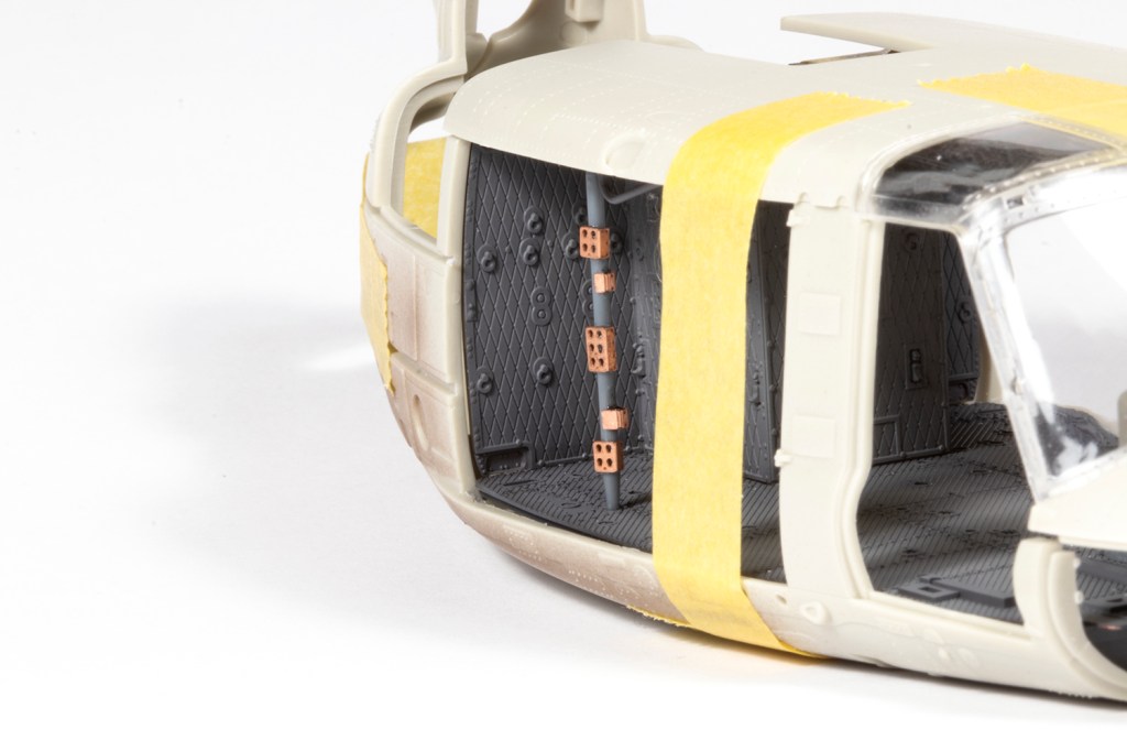
The final parts of the interior jigsaw were those PE pillars that unite the roof and floor behind the pilot seats. Besides being incredibly flimsy, installing them so there were no gaps anywhere was impossible for me. I did the best I could – and fortunately where they meet the floor is not that visible – but in the end I got them in, even if I’m not quite sure how.
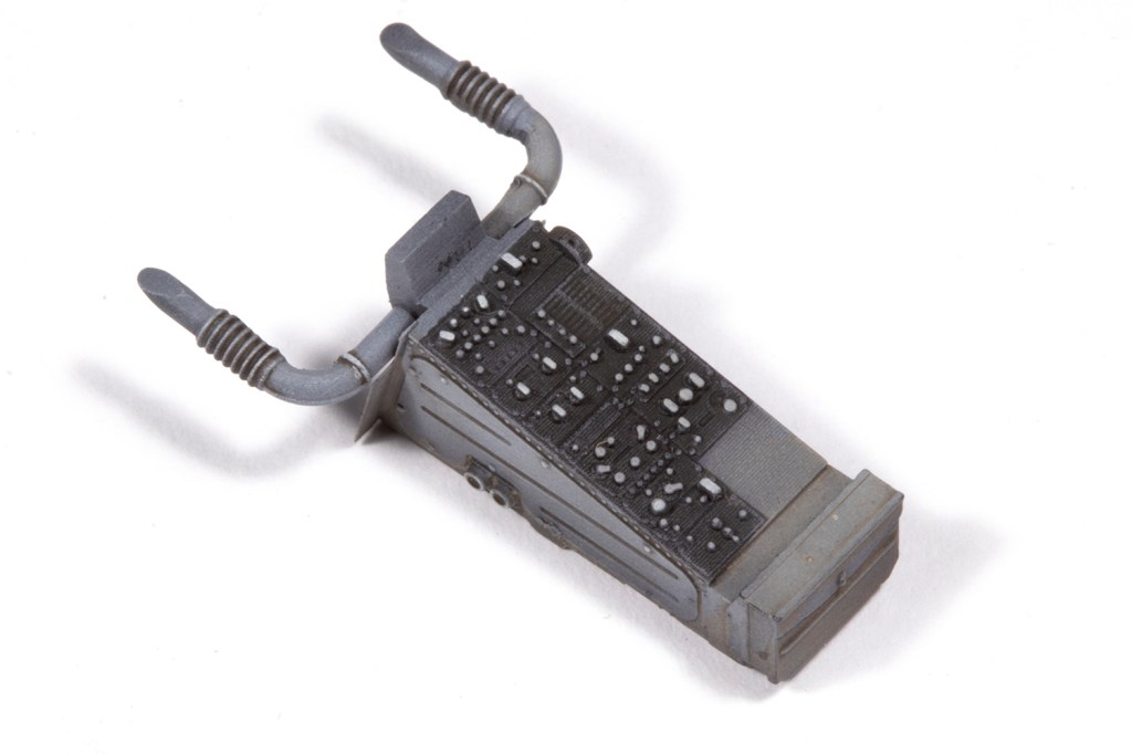
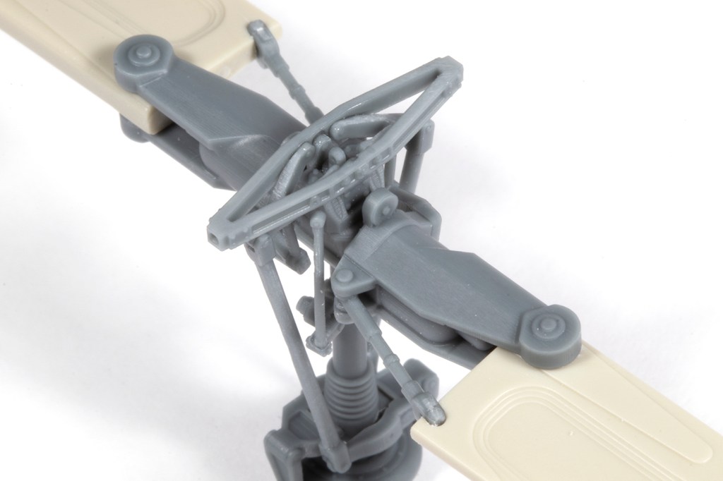
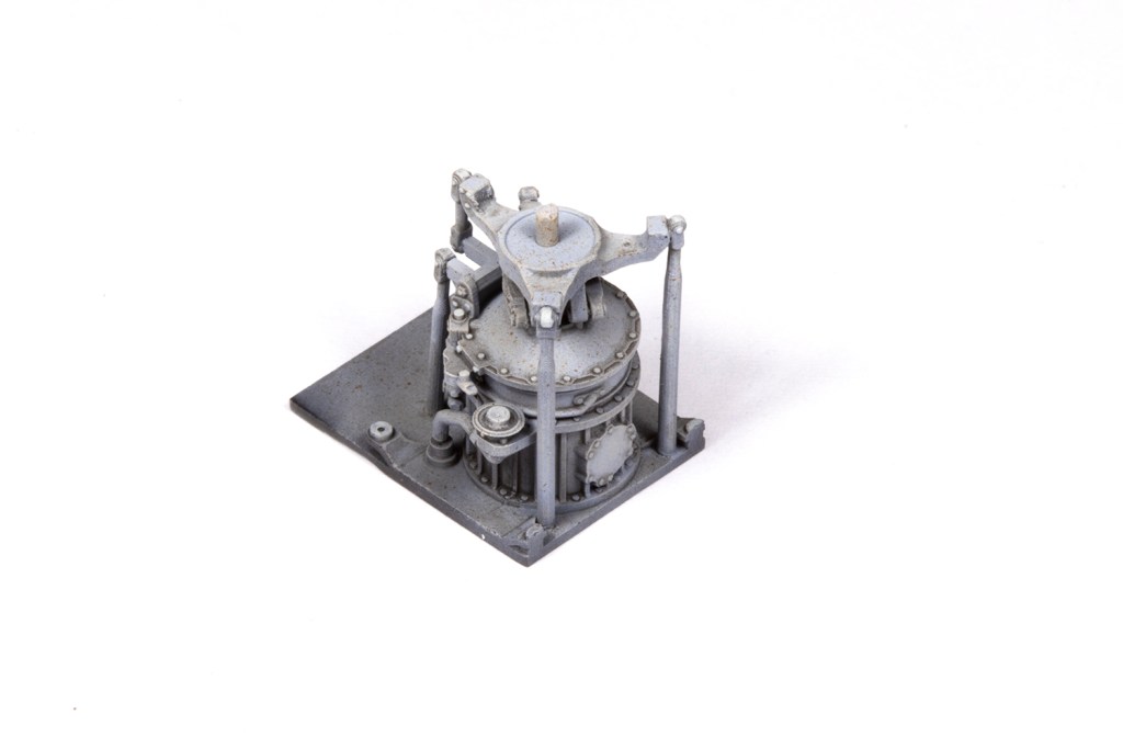
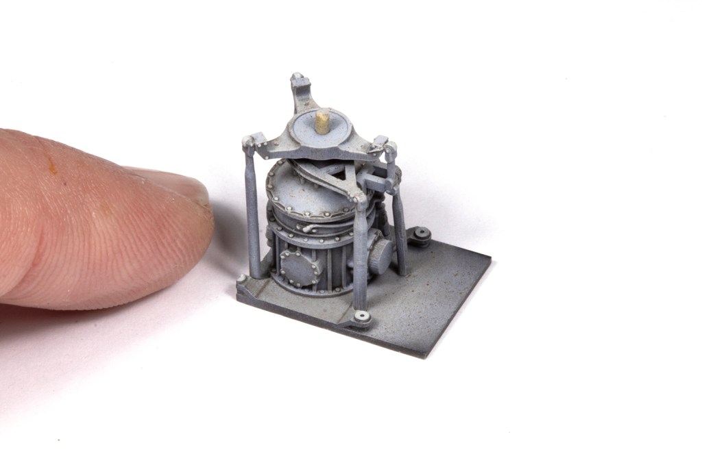
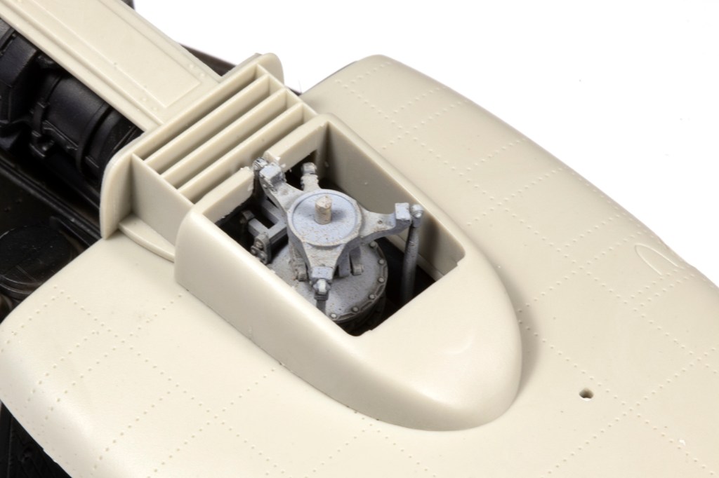
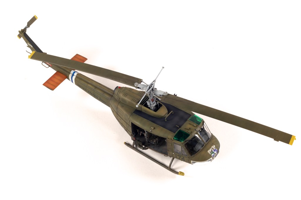
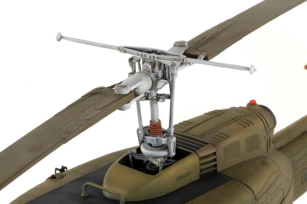
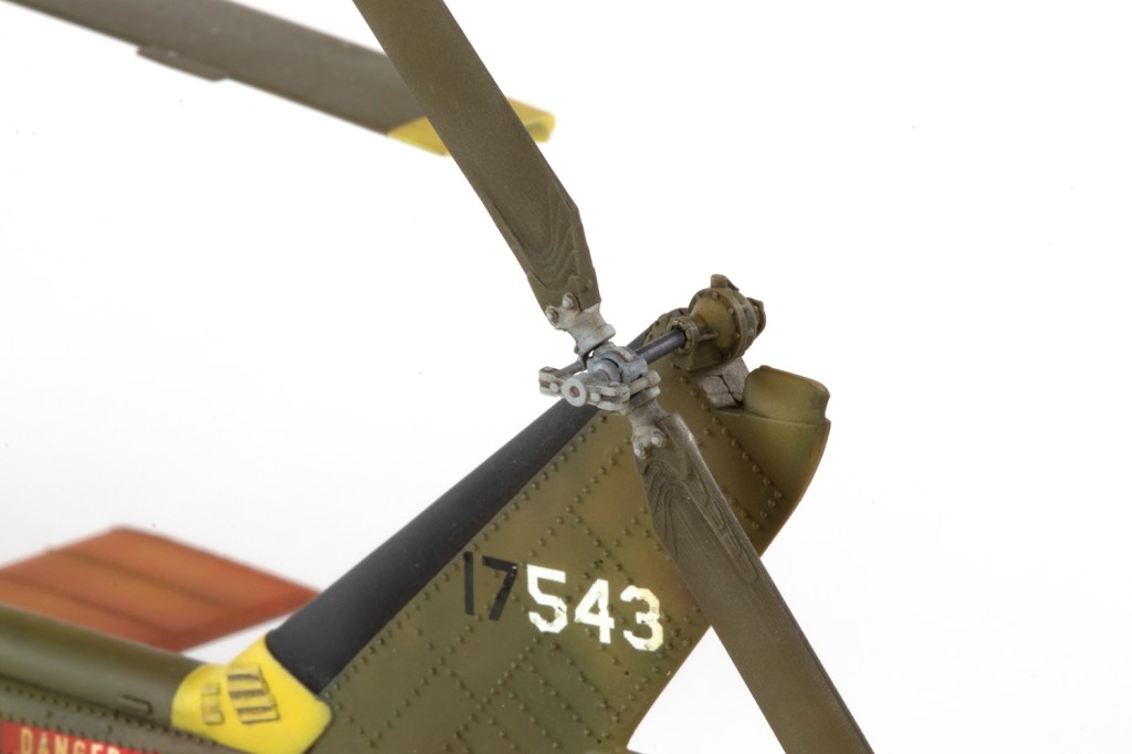
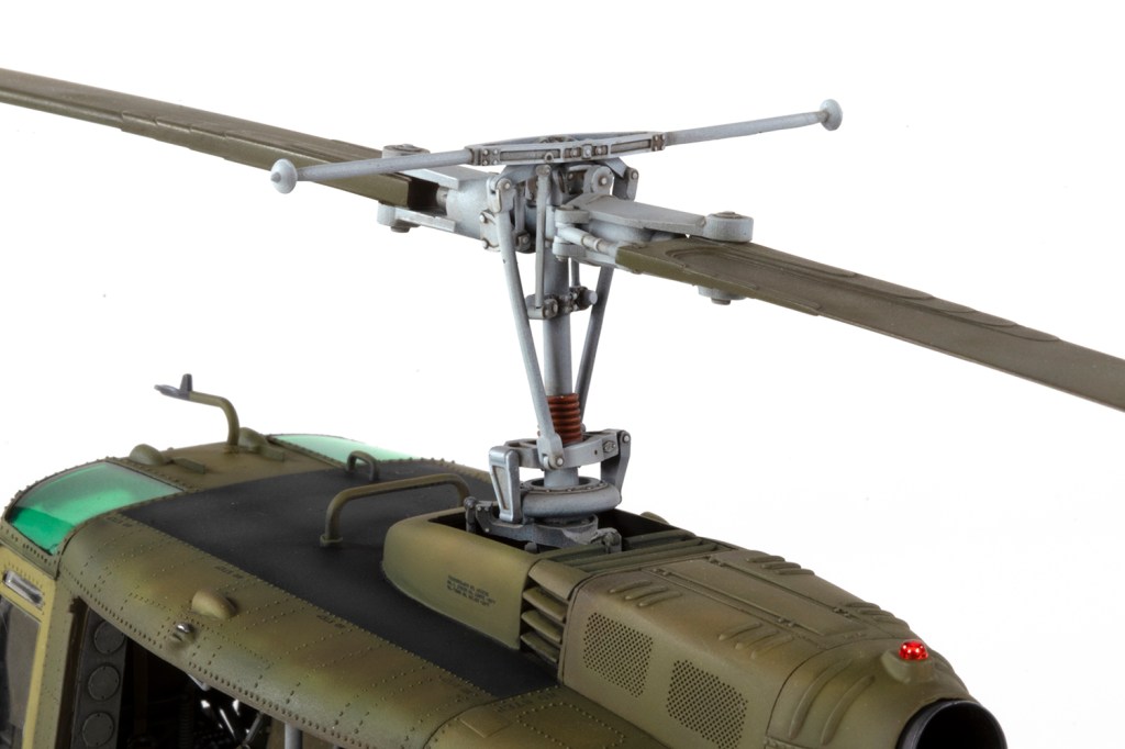
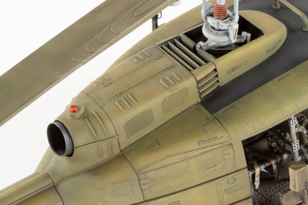
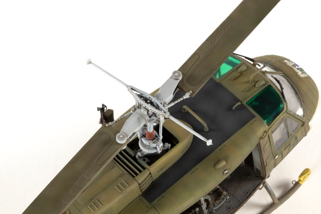
Whilst I had been fiddling with the interior, I’d been working on other parts. ResKit’s main rotor is a pretty complex assembly, and despite my best efforts I couldn’t quite get all the parts to unite properly. It also doesn’t seem to work that well with the interior set because when I was done, the base of the rotor mount sat way too low in the fuselage, and also too far aft, meaning I had to butcher some of the kit parts to get it to fit. The design makes it hard to get the two blades lined up with each other. Mine weren’t quite parallel, and I was prepared to live with it until I accidentally snapped a blade off late on in the project, and pinning it back on again afforded me to the opportunity to ensure they were straight second time around. On my next Kitty Hawk Huey I intend to use the kit parts and see if the difference from the aftermarket is really that noticeable.
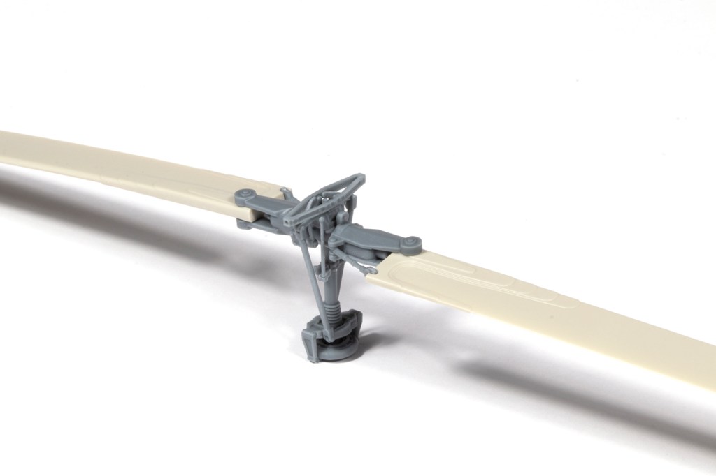
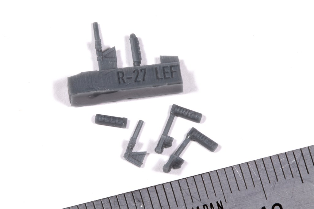
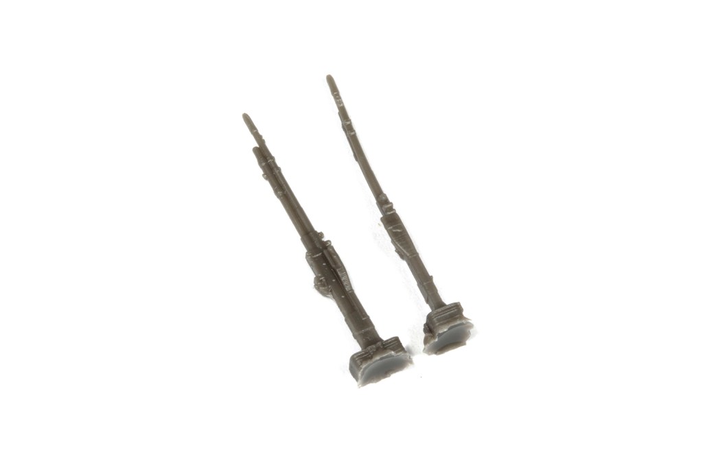
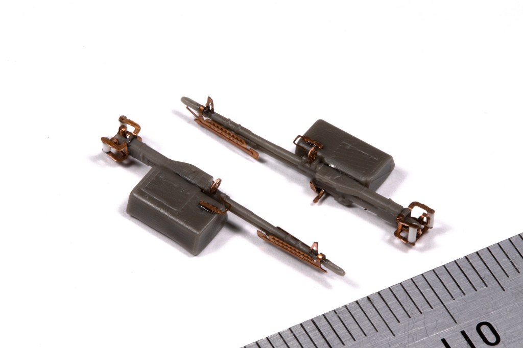
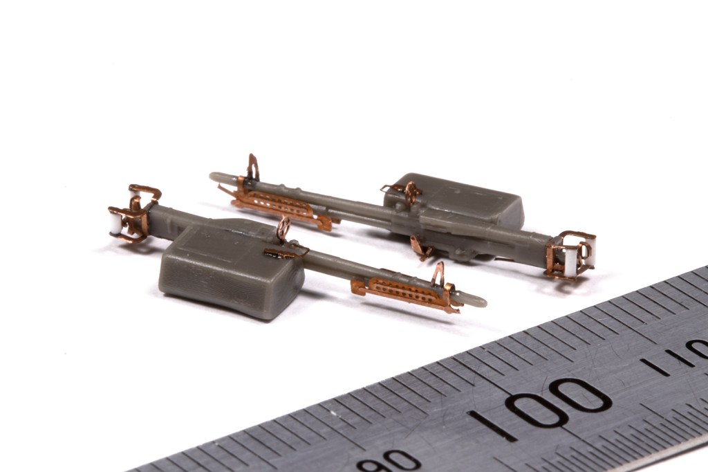
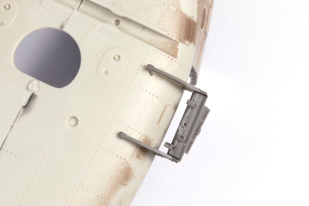
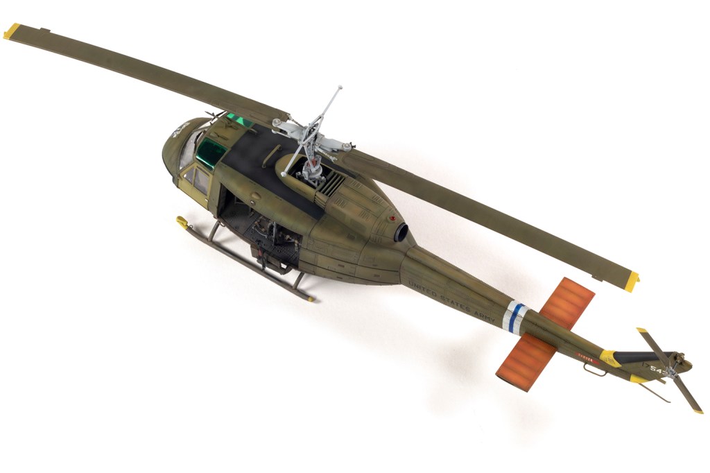
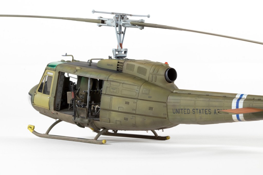
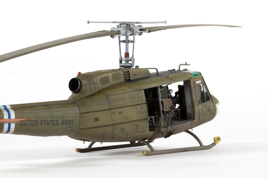
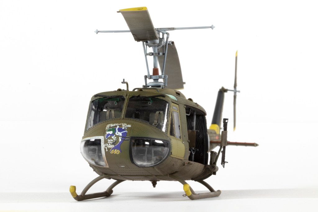
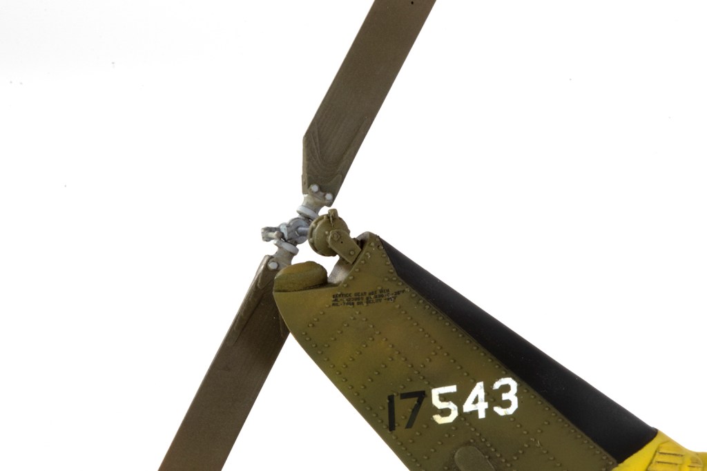
ResKit’s tail rotor and exhaust are simple additions. The guns, on the other hand, are right at the limit of what I can cope with, especially the very tiny PE parts that need to be added to the resin gun bodies. Bending the trigger mechanisms was a case of taking a deep breath and hoping for the best; I could barely see what I was doing, but the final result wasn’t bad. The bigger problem with this set is that I could not get the gun mounts to fit the fuselage sides at all, and I gave up on using any locating holes and pegs. The final geometry is thus not very accurate. Most Hueys on the ground show the guns stowed pointing downwards, which was easy enough to pose by installing the tiny PE gun mount in this orientation. ResKit provide some lovely metal ammo belt feeders, but since I couldn’t see these on many photos, I didn’t use them.
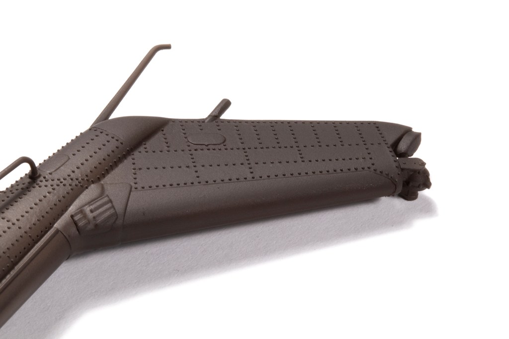
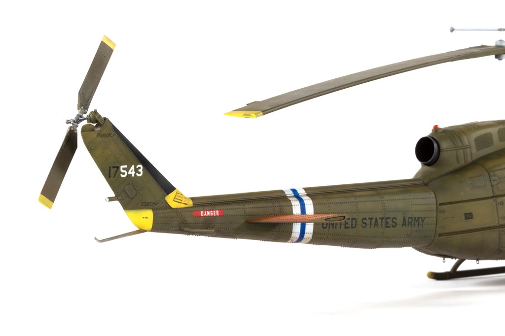
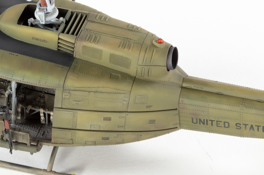
I had one excellent photo of the airframe I was modelling which allowed me to determine which kit parts to miss off: the wire cutters (part C50), roof aerial (C45), part C30, the ‘rails’ around the windscreen (B23/24) and the large roof-mounted blade antenna (C4). The latter is a strange omission as it was present on every single UH-1D/H I looked at, including 17543 at other stages of its life. It’s definitely not in the photo though!
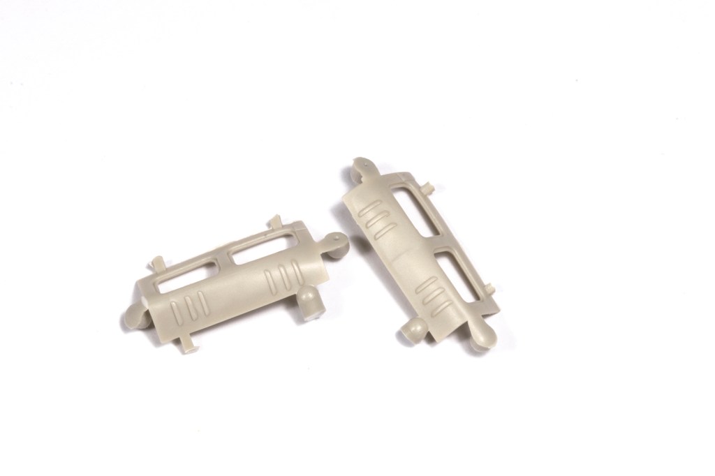
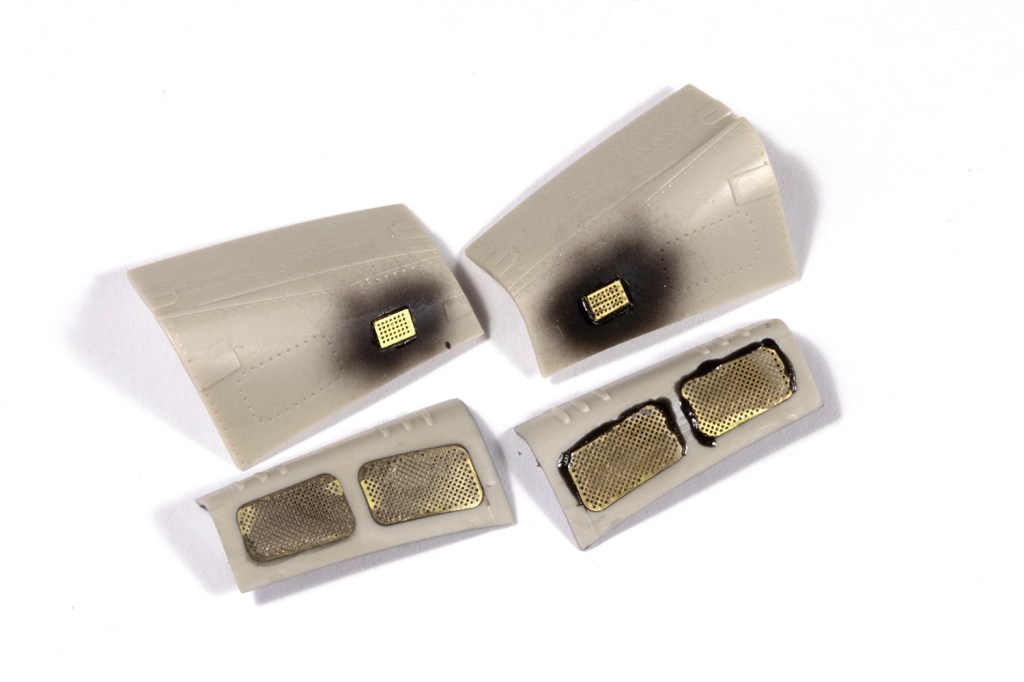
Kitty Hawk provide quite a few engine parts and the engine cowling doors can be posed open. I don’t like exposed engines in general, so closed everything up but did include the engine in case it was visible through the PE screens fitted to the cowling doors. It wasn’t.
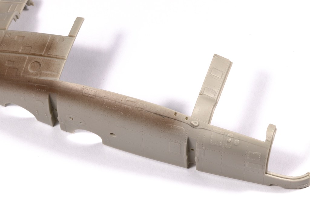
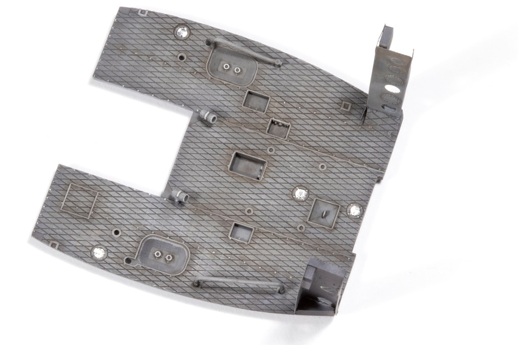
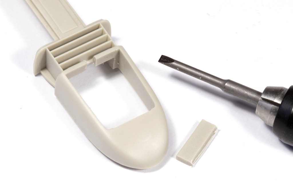
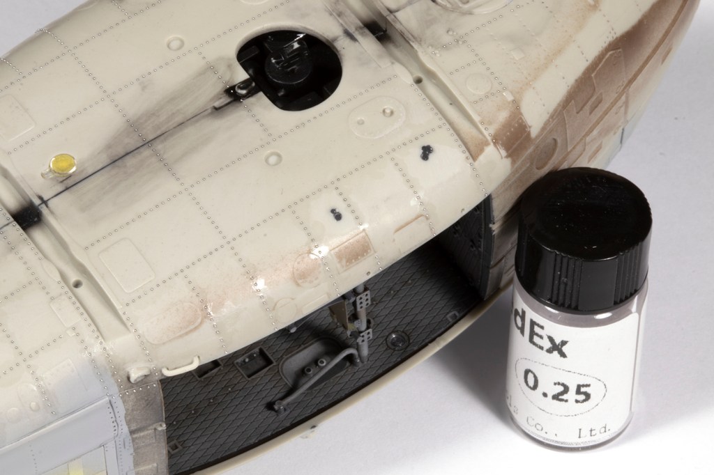
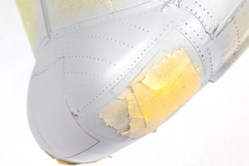
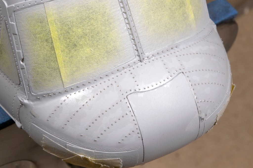
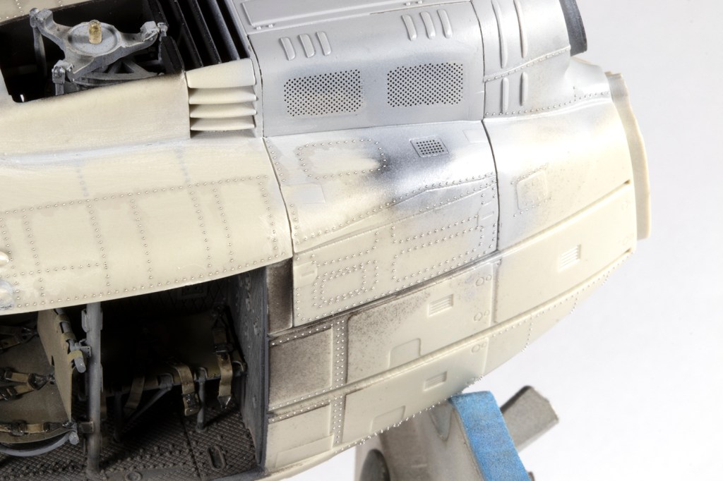
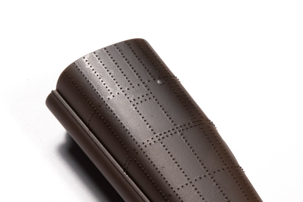
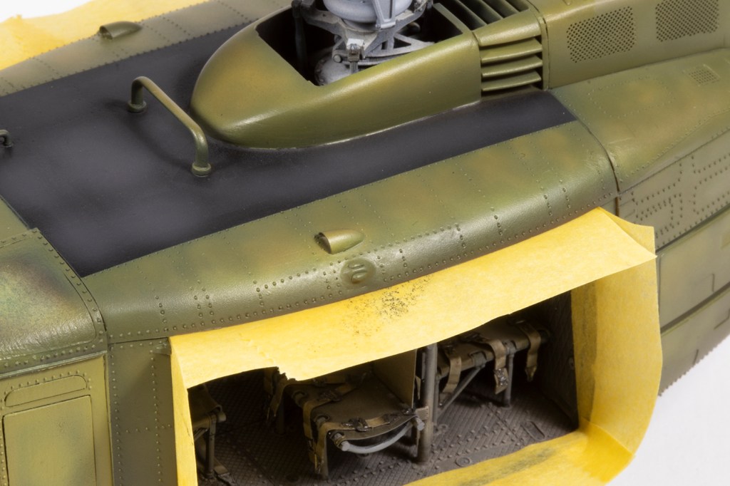
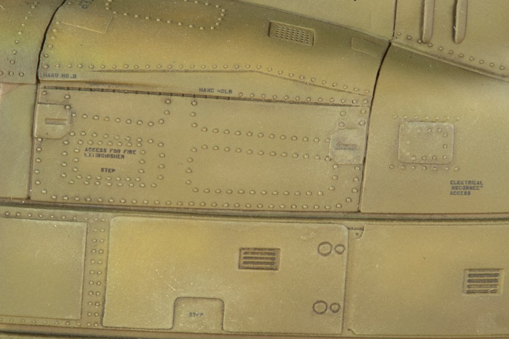
I now turn to the other major feature of this project: the rivets. It is de rigueur for helicopter to kits to have recessed rivets, even when the real thing usually had nice raised rivets, and I understand why this is. But a few years ago, I saw French modeller extraordinaire Fanch Lubin making a 1/35 SH-60 on Facebook, and he used 0.3mm solder balls placed in each recessed rivet hole to reproduce raised rivets. I thought it was mad, and knew I would have to try this one day. At Scale Model Challenge last October, UK modeller extraordinaire Andy Evans described how he was using this method on his H-60, and I was convinced: the time had come to do this in 1/48.
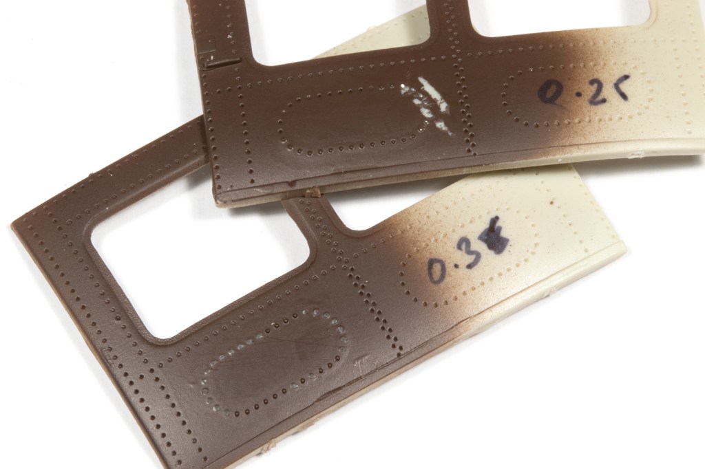
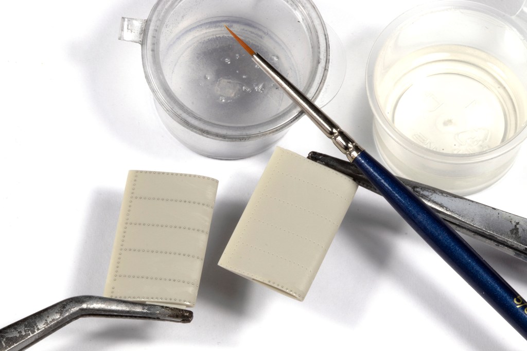
The first thing I needed were solder balls. After a short perusal of eBay, I had ordered bottles allegedly each containing 12,500 solder balls from 0.25-0.6mm in 0.05mm increments for about £12. Andy’s method was to dip them in Johnson’s Klear and then manipulate them into each hole with a brush. I experimented on the kit doors (which were going to be discarded anyway) using the 0.25mm and 0.3mm sizes. The method worked well, but the 0.3mm balls were a bit too big and not terribly robust after painting. I started with the 0.25mm diameter on the tail boom.
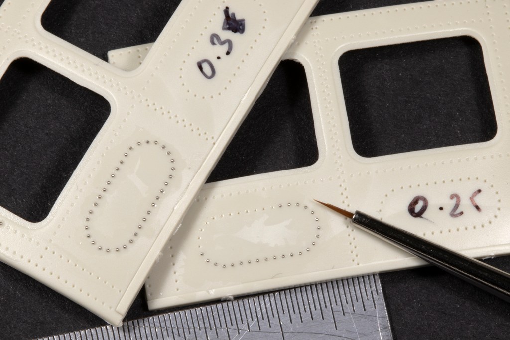
There are a couple of complicating factors. One is that the moulded rivet holes are not consistent in diameter or depth across the airframe, even along the same run of rivets. A second is that the Johnson’s Klear can thicken up quite fast and leaves a lumpy surface finish. After getting more experienced at application, I discovered it was critical to keep the Klear quite fresh and to apply as little as possible. Rather than dipping the balls in the Klear, I dabbed a tiny amount of Klear in the hole and then used a very fine brush with some Klear on it to pick each ball up (I decanted them into a small dish) and locate it in the hole. The ball tends to get ‘sucked’ into the hole quite easily, except near the edges of parts where the rivets holes tend to be a bit washed out and lack depth.
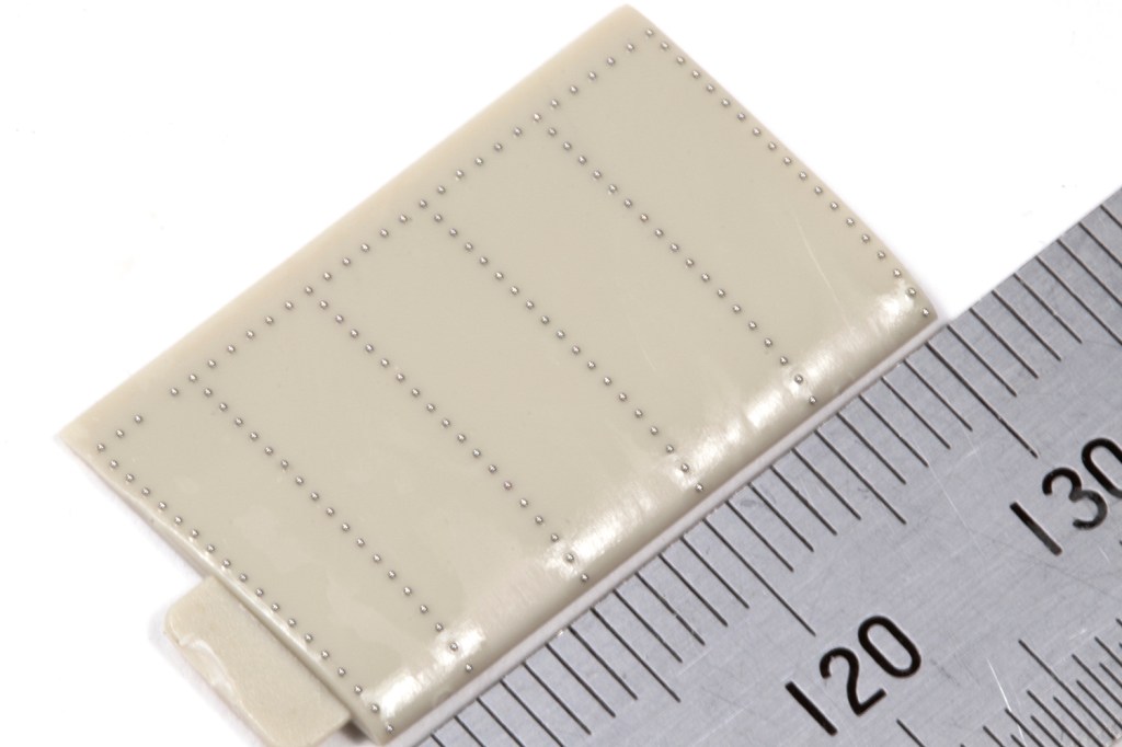
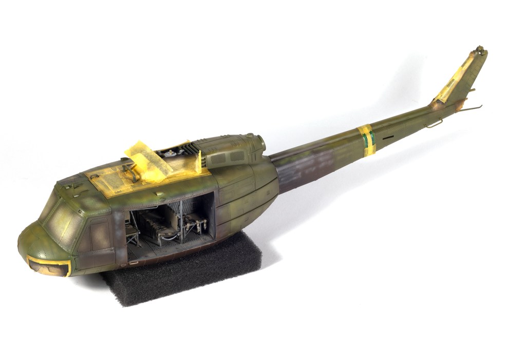
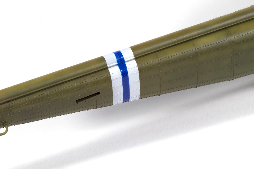
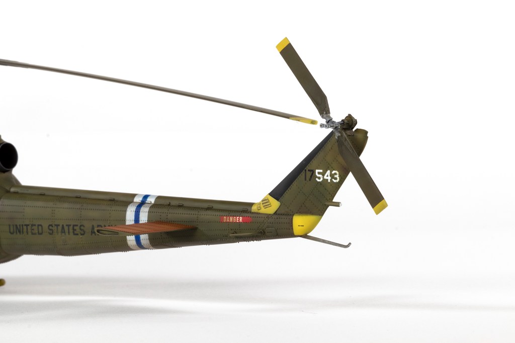
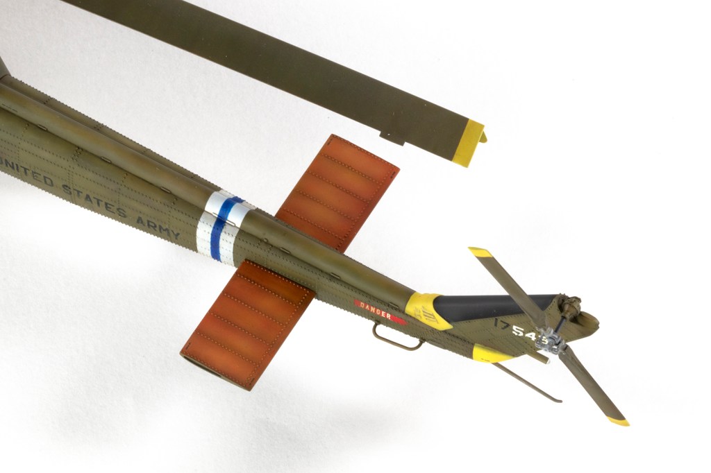
I started with the tail, which I kept separate from the main body, and also after I’d cleaned up all the seams. The applied solder balls are fragile, so I wanted to minimise handling once they had been added. When the tail was done I was struck by how overscale the rivets were. It is inevitable that they would be – true scale rivets are impossible in 1/48 – but the rest of the main fuselage was done with 0.2mm balls, which are slightly better. This did not take as long as I feared and was a very satisfying process.
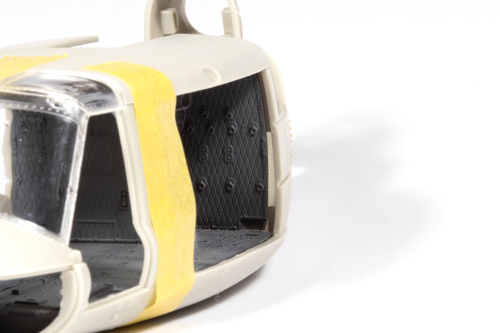
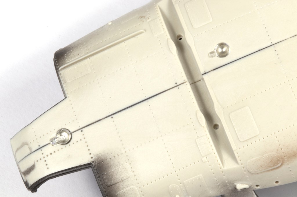
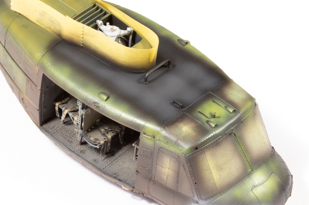
With the rivets done on the tail, I assembled the main fuselage. Getting the doors, windscreen and roof together was difficult, I suspect because of the aftermarket interior. Some strip plastic and filler helped, and you can make life easier for yourself if you open the front doors. Careful planning was necessary to ensure seams were dealt with before the rivets were applied to the main body. On the roof I filled the recessed rivets where the black walkway marking was going to go.
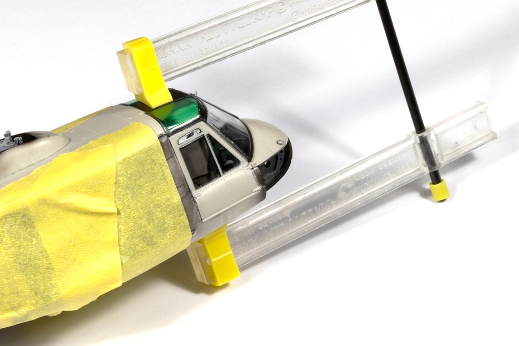
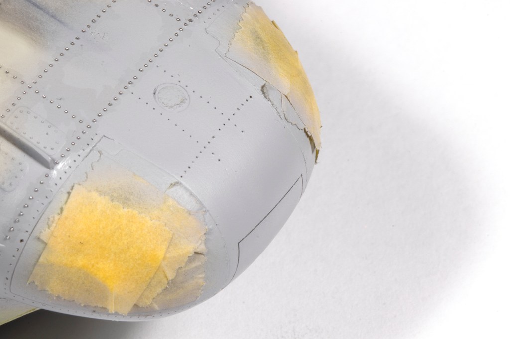
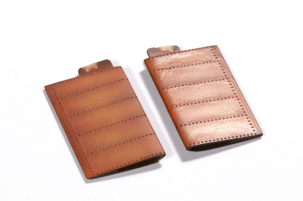
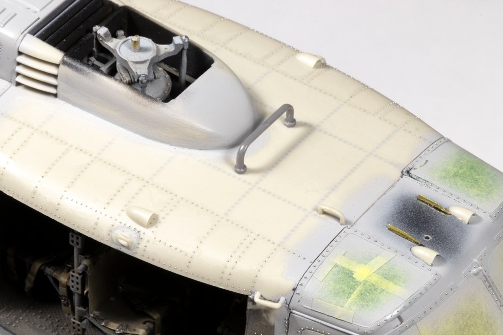
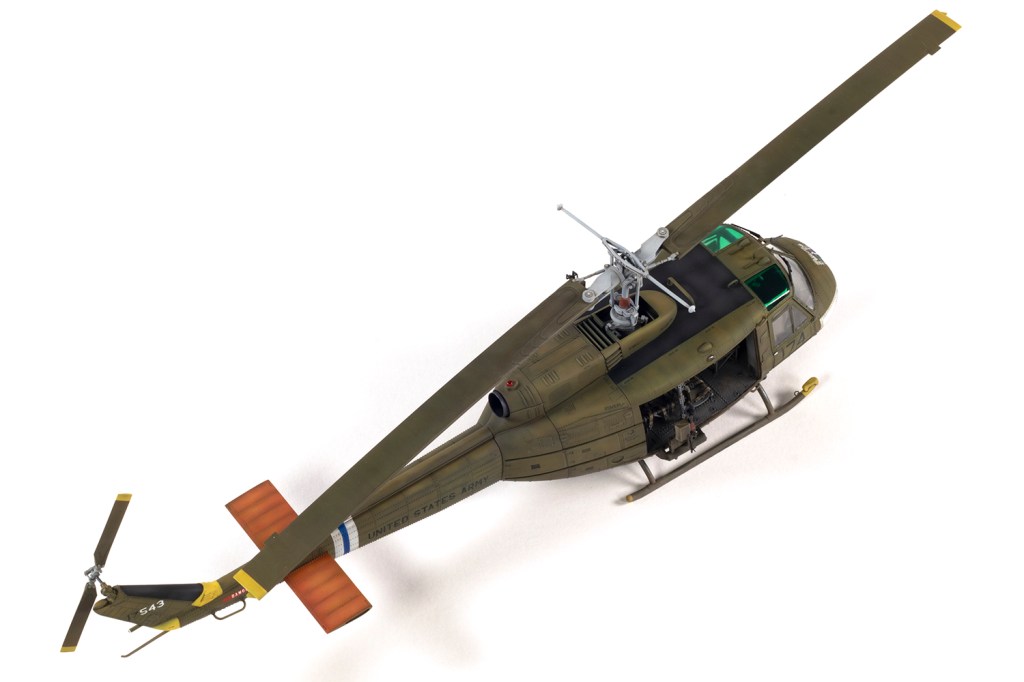
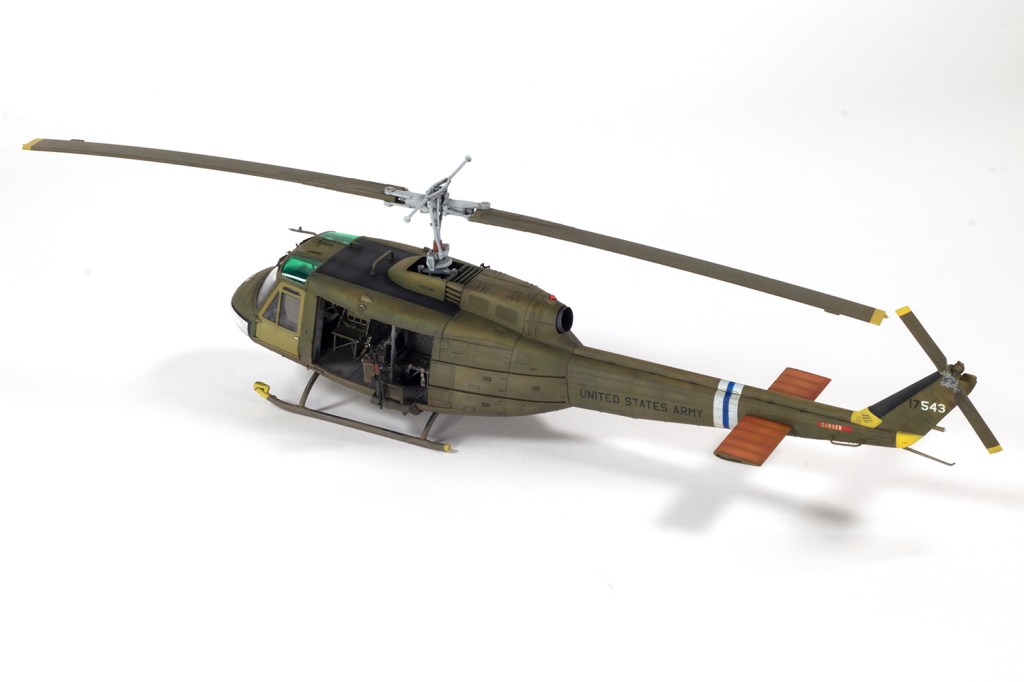
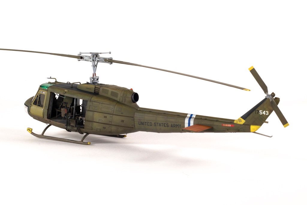
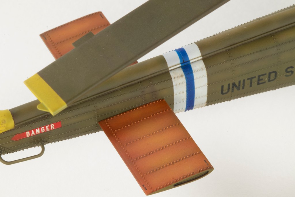
Keeping the tail and main body separate for the time being (to minimise damage to the rivets), I embarked on painting. This aircraft had a new starboard front door, in a much lighter green, and some yellow panelling on the tail, as well as orange upper elevator surfaces and a white and blue tail stripe, all of which were very appealing to me. I primed the model with Mr Metal Primer in an effort to make the paint stick better to the metal rivets, although I’m not sure if it really made any difference. Over this went a healthy coat of Mr Mahogany Surfacer 1000.
This revealed that lumpy surface where the Johnson’s Klear had been applied around each rivet. In experimenting with some thick coats of VMS Matt Varnish I discovered this lumpiness could be made to ‘disappear’, but the next time I try this method I will experiment with a different adhesive for the rivets which I hope will give a smoother finish.
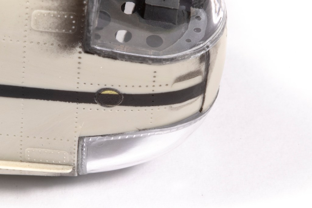
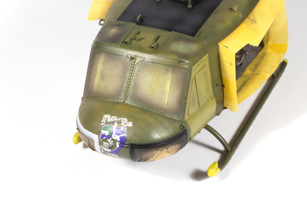
I was extremely nervous about masking the tail stripe and borders around the nose windows, since the tape would be applied directly over the rivets. My fear was removal of both rivet and/or paint when the masking was taken off, and I thus gingerly applied the Tamiya tape. In the event I lost one rivet, which was easily replaced. I’m sure if you went over the finished model with a magnifying glass you would find a couple of missing or misplaced rivets, but the overall effect was enough for me.
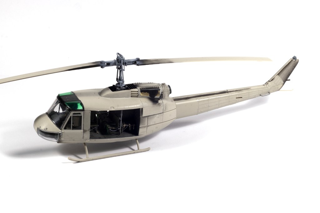
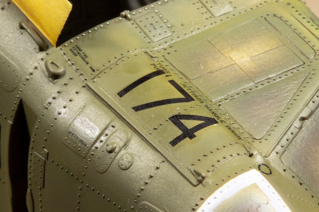
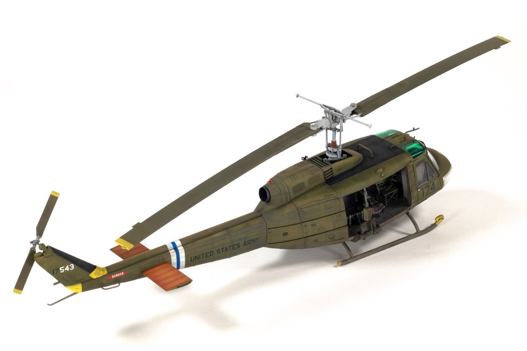
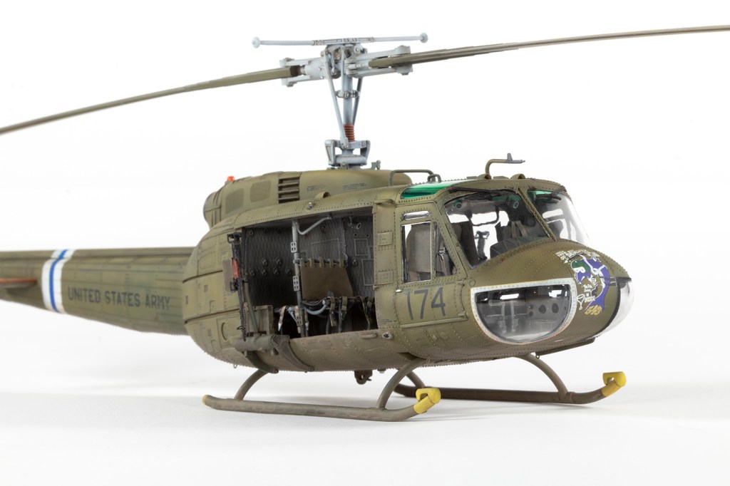
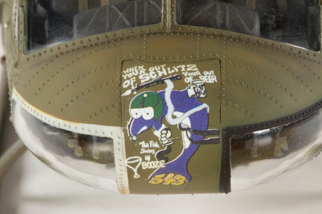
Mr Color 304 was the main shade used for the Olive Drab. Directly onto this paint I used decals from Werner’s Wings. Again, I was nervous of this, because the UNITED STATES ARMY legends and serial numbers on the tail would need to settle over some pretty large rivets. In the event, my fears were completely unfounded and these decals settled down incredibly well over the surface detail by simply floating them on in a puddle of Mr Mark Setter. The Werner’s Wings set is primarily a stencil set with some corrected markings for the kit options. The nose art needed to come from the kit, and over the complex curve of the nose, this settled down well: WHEN YOUR (sic) OUT OF SCHLITZ YOUR (sic) OUT OF BEER…THIS FISH SWIMS IN BOOZE with the gun totting dolphin that characterised 174th AHC ‘slicks’.
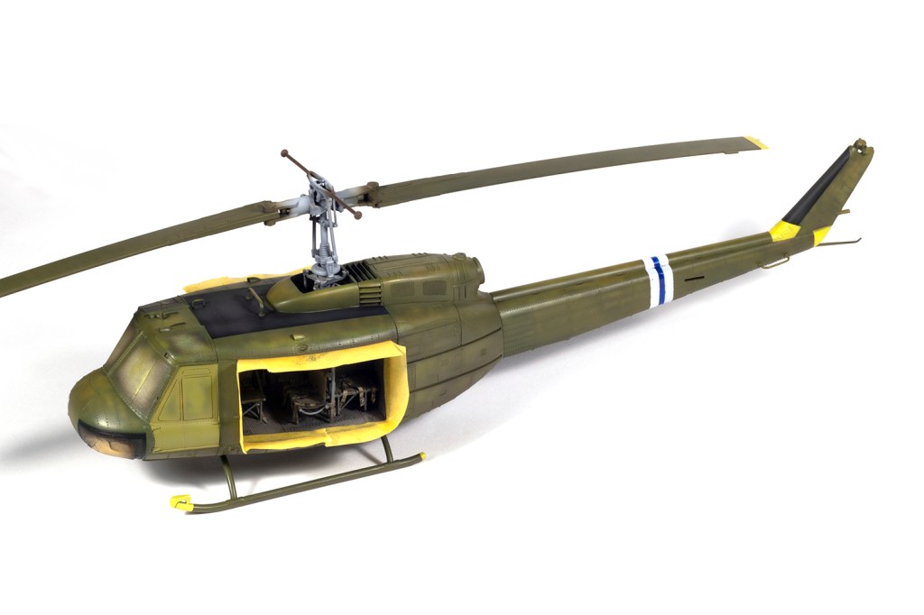
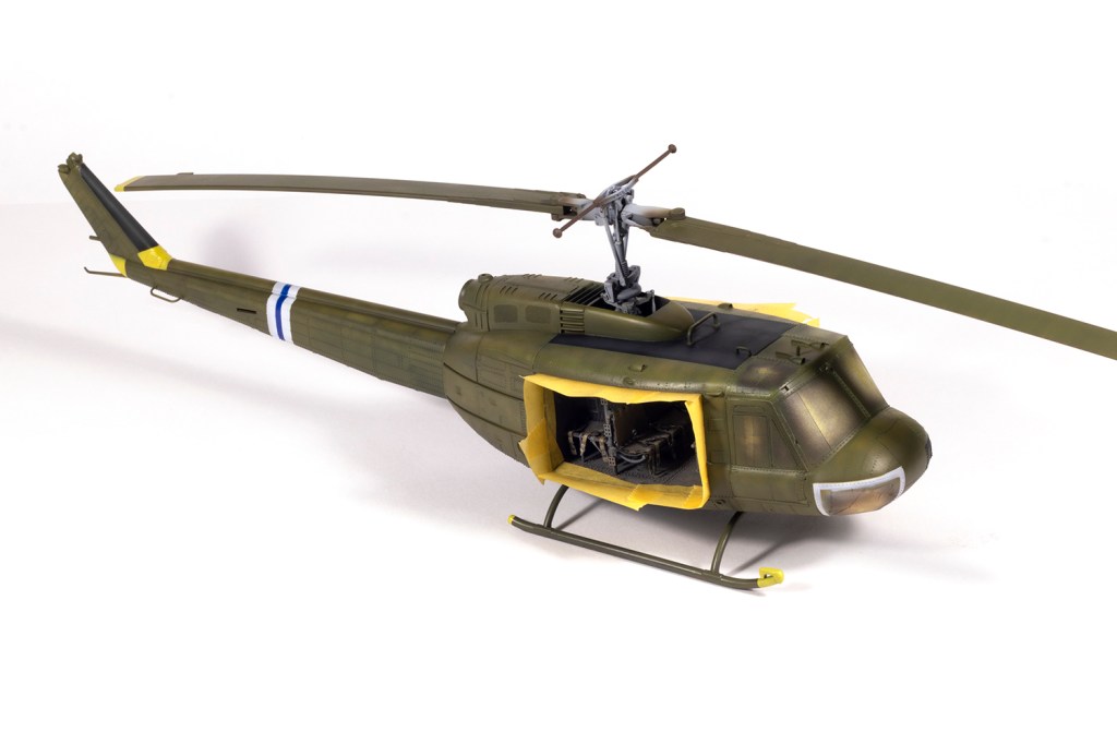
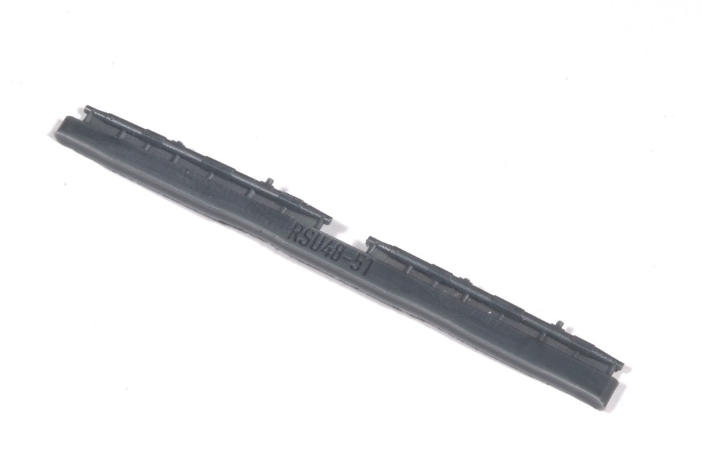
I kept the weathering fairly light to avoid damage to the rivets. Final assembly consisted of adding some tiny PE parts under the fuselage, attaching the skids (make sure you get the front and rear cross members the right way round – they’re both labelled A26, but are not the same!), followed by the guns and rotors.
I had tremendous fun with this project and I’d do it all again. The ResKit aftermarket is truly challenging, but very rewarding, and the basic kit is good enough. I loved adding the rivets, and if I can find a better cement, I think I could love it more. I’ve already started the Kitty Hawk UH-1N and need to buy more solder balls.
Year bought: 2018 (eBay)
Year built: 2026 (New Addington, Croydon)
Back to home.
