with Black Dog resin pylons, Master metal pitot and Xtradecals decals
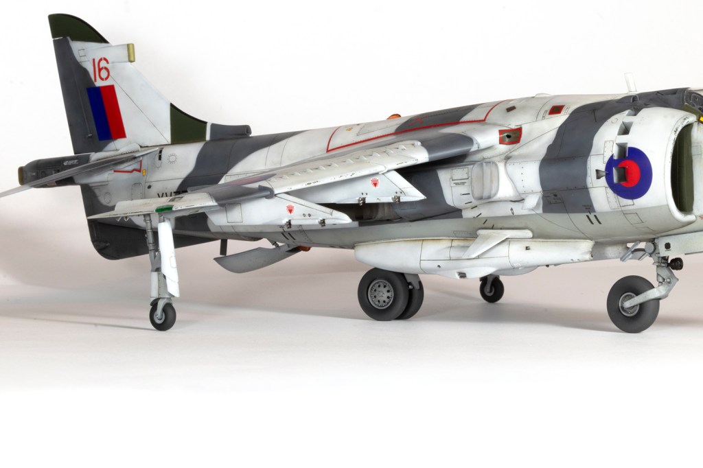
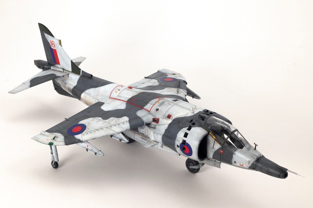
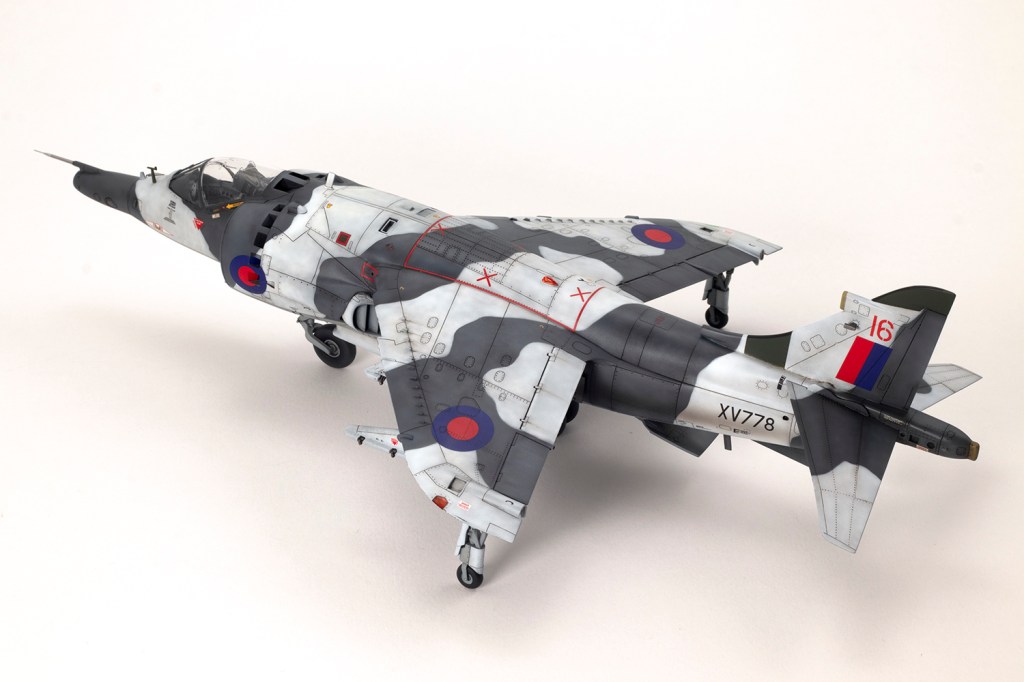
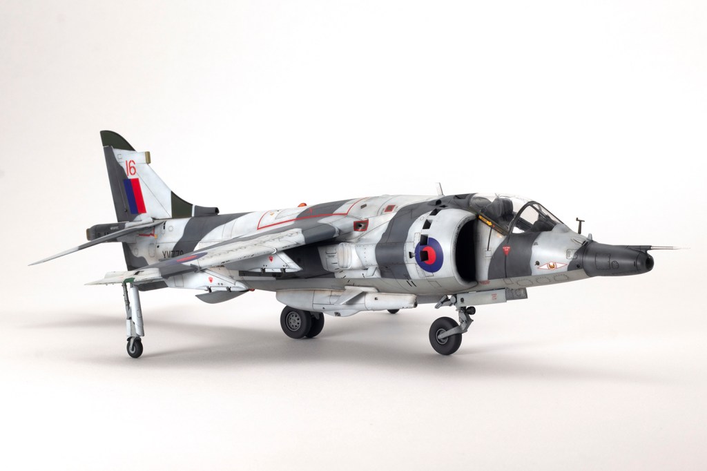
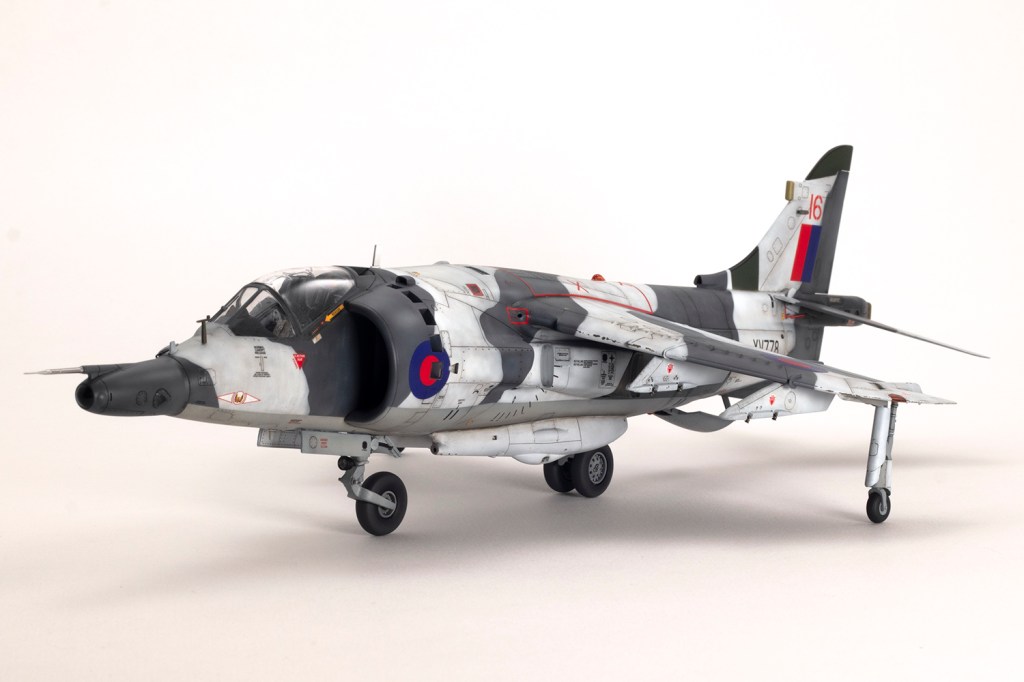
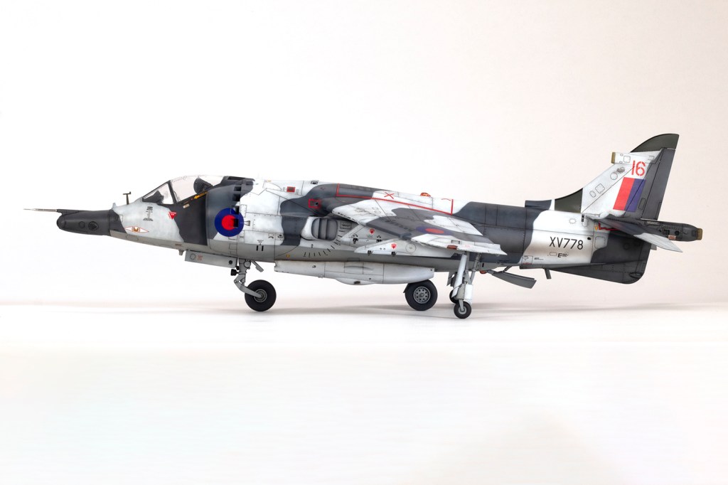
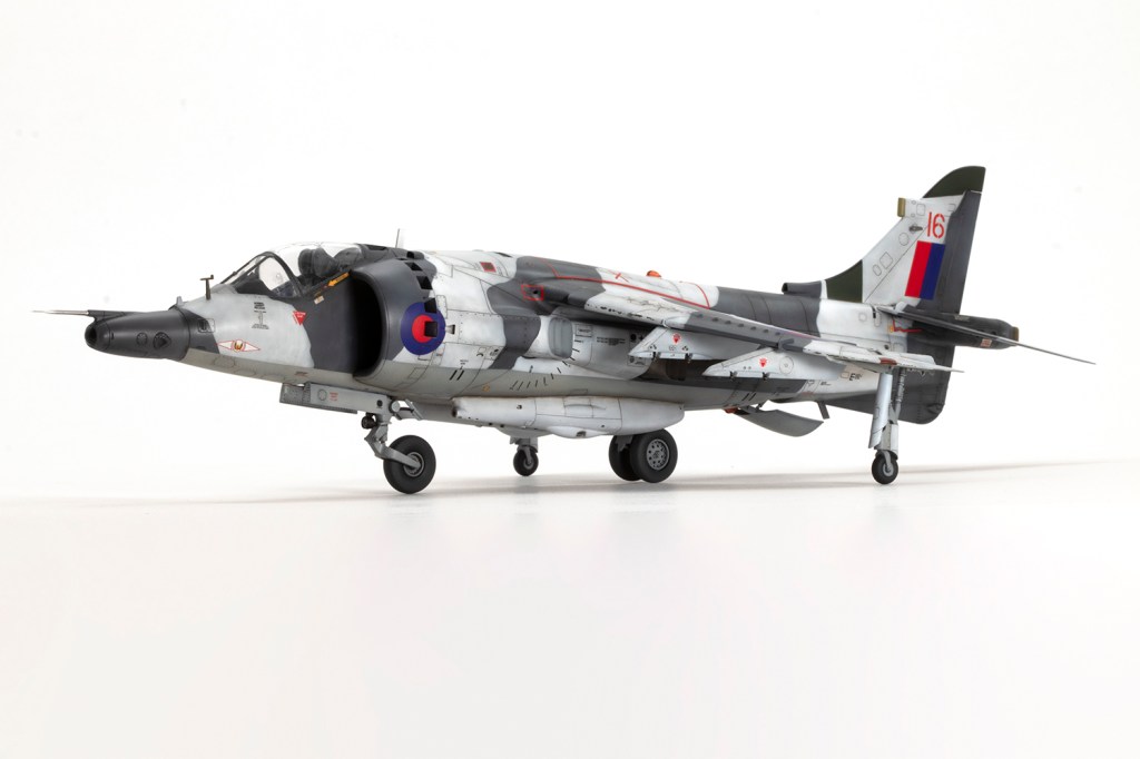
1(F) Squadron, Royal Air Force, Norway 1979

One of my vivid mental images from growing up in the 1980s, surrounded by models and posters of jets, is of first generation Harriers flying at low level over Norwegian snow in winter camouflage. I’m sure I had an Airfix kit in the white and grey scheme, and whilst I think the Snoopy-nosed GR.3 makes a rather pretty aeroplane an ugly one, when Kinetic released their kit back in 2020 I knew I’d be making it in this scheme.
As soon as I received the kit, I purchased Xtradecals with markings for XV778 in winter camouflage from 1979 and then approached the IPMS Harrier SIG for more information. If you’re making a Harrier, there’s one thing I can’t recommend enough: join the Harrier SIG. I was provided with way more information than I could cope with on the Kinetic kit, Harriers in general, and specifically those that flew in the Arctic over the years. It turned out to be more complicated than I imagined.
In the box, the Kinetic ‘Gold’ kit is impressive, but in the making, less so. You are given an abundance of unused parts, of which many are duplicates from earlier versions of the Harrier which Kinetic then retooled to a slightly higher standard. Aside from the fact that unused parts are never mentioned, the instructions are adequate for guiding you through your choices, and the input of the SIG is clear, but you need your wits about you to make sure the correct pylons, aerials, nose and tail are used. The moulding is less ‘Gold’ and more ‘Bronze’ with some significant mould defects in the rear fuselage (lots of scratches), a pebbly surface in some areas, ‘ghost’ recessed detail clearly inherited from previous iterations of the mould, and incomplete panel lines towards the edges of the major parts.


Decisions need to be made early on as to which variant you want to make. Don’t be ignorant, like me, and assume the GR.1/GR.3 distinction was all about the nose and the tail – the change in designation was to do with the engine fitted, and Kinetic provide markings for a nice selection of GR.1s, early GR.3s with the pointy nose, and later GR.3s with the snout, including a Falklands option. Rather than follow the instructions, I started by grafting the nose and tail halves to their respective fuselage sides. The fit was excellent and boded well for the future. More fool me; it was all uphill from here.
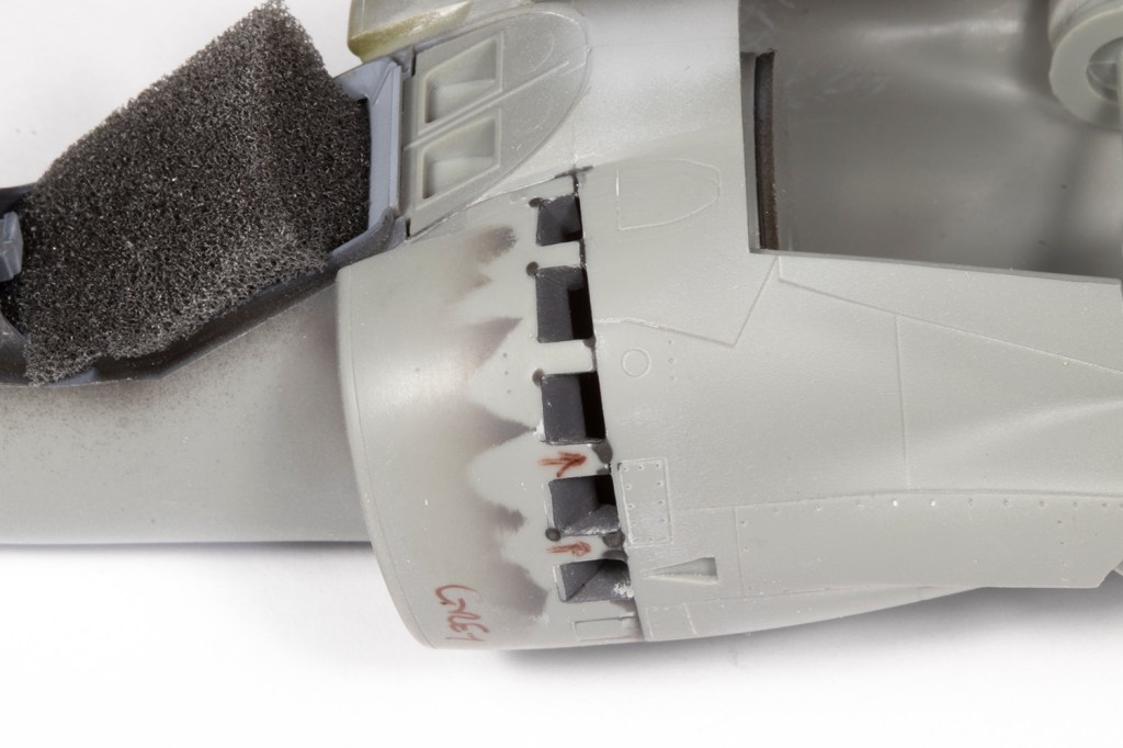
Let’s start with the wings, which are probably the weakest area of the kit. After priming the parts in black and sanding the surfaces them back to remove unwelcome surface texture, the wings need modification at the tips so the upper and lower halves close correctly. Under the dog teeth on the leading edge, Kinetic have moulded some recesses which need to be filled and shaped. This is most challenging for the inboard dog tooth since the shape will depend on the join with the fuselage. There are some significant gaps on the underside where the wing meets said fuselage, which some modellers like to solve with a spreader bar, but the tension that puts the lower joint under stresses me out, so I went for plastic shims and oodles of filler instead. It’s compounded by being difficult to access due to the nozzle fairings and high-mounted wing.


You also need to relocate the wing pylon locating holes, assuming you care about such things. The outer pylons need to go outboard by around 1.5mm and rearward by about 2mm. The inboard pylons need to be moved back around 1.5mm. I had a Black Dog Harrier Update set lying around, which is reserved for a Kinetic Sea Harrier FA.2 I intend to make, but this included some RAF inner pylons that would be unused. I used them here, but did not modify the shapes of the outer pylons – those in the kit are too short. The Black Dog set has nice details, but the moulding quality is, shall we say, dated?

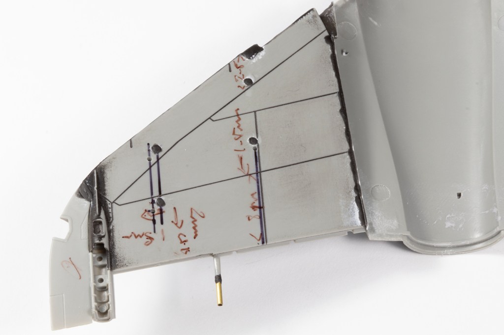
You also need to relocate the wing pylon locating holes, assuming you care about such things. The outer pylons need to go outboard by around 1.5mm and rearward by about 2mm. The inboard pylons need to be moved back around 1.5mm. I had a Black Dog Harrier Update set lying around, which is reserved for a Kinetic Sea Harrier FA.2 I intend to make, but this included some RAF inner pylons that would be unused. I used them here, but did not modify the shapes of the outer pylons – those in the kit are too short. The Black Dog set has nice details, but the moulding quality is, shall we say, dated?

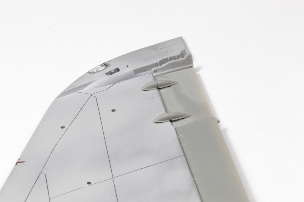
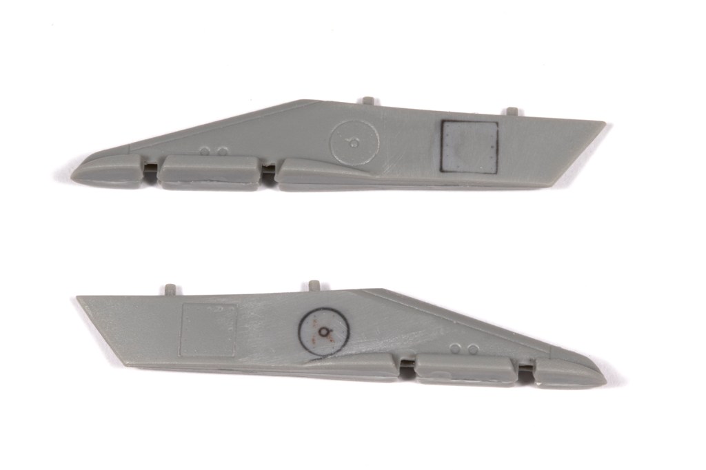
We’re not done with the wings yet, as separate control surfaces are provided. I know most modellers love them; I just wish they were moulded neutral since that’s how I prefer my planes (unless they were always deflected when at rest, like on a Hornet). It’s not a problem if they fit well, but here they don’t: the wings are way too thick at the trailing edge compared to the ailerons and flaps. ‘Aha!’ I thought, ‘I don’t really care about that, as long as they are level on the top!’ I did put a little elbow grease into thinning the trailing edge parts until I got bored and then in my haste just glued the wing halves together. And then my error became clear: because of the step from the wing to the aileron lower surface, the actuators don’t fit. At all – and never mind the missing locating holes for the moulded pegs! I resorted to a lot of filler to smooth the actuators in, but next time I’ll just have to do it properly and thin the wings much, much more. Final additions were some brass tubing slipped over the plastic fuel jettison pipes and the wingtip lights, which are a very poor fit and thus could not be left to the end, but were blended in with superglue during construction.


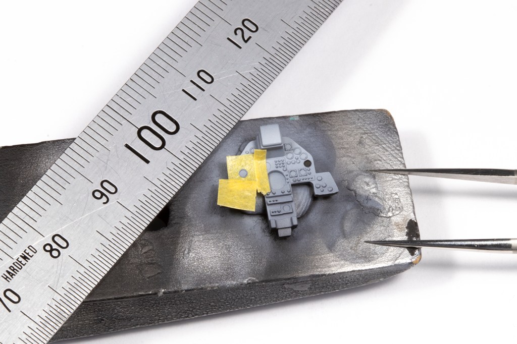
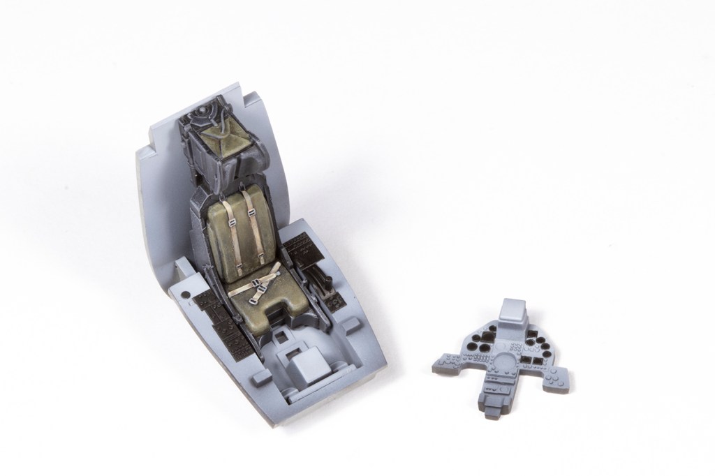
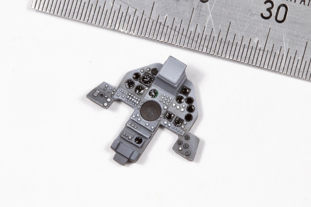
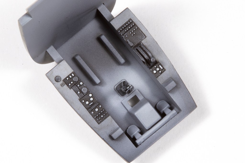
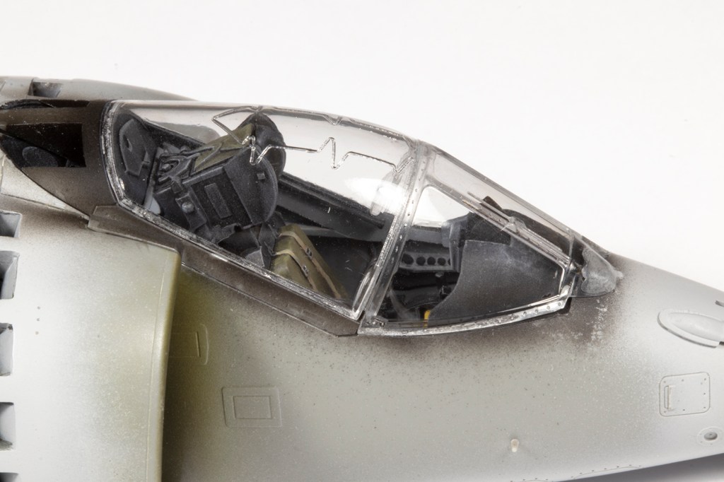
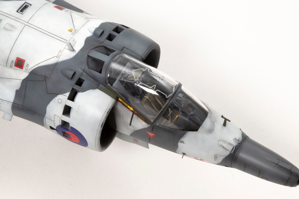
On to happier matters. The cockpit was perfectly fine for me from the box, including the seat which was adorned with PE straps from the kit. The tub is nicely detailed and I airbrushed it a generic mid-grey (in this case Mr Color 306) and masked the panels off so I could spray them black. I did the same with the instrument panel, but used some HIQ die cut circle masks to allow the dials to be individually airbrushed. I really enjoy painting all the raised detail in a light grey colour and used some generic Airscale decals for spurious instrument gauges.


In addition to the cockpit, various modules need to be completed prior to joining the fuselage halves. The rear undercarriage/airbrake bay is nicely detailed, but as I was going to close the doors, it would be invisible. Nevertheless, I used it as an opportunity to practise weathering the white finish with some brown and black ink washes. The doors don’t fit well in the closed position, with nothing to mount to, so I attached each door to its respective fuselage side and backed the very fragile joint with plastic strip.

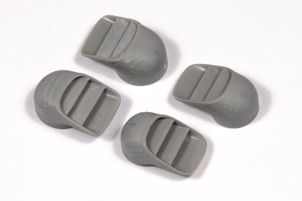
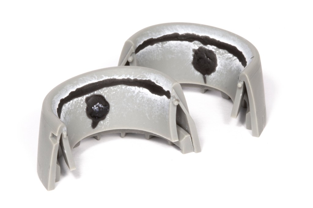
If you desire moveable nozzles, you can add the mounting system now, but they fit fine from the outside anyway, so I just omitted the mechanism. The nozzles themselves are really nicely produced as single pieces, which require some clean up but I was delighted there are no awkward seams to deal with.
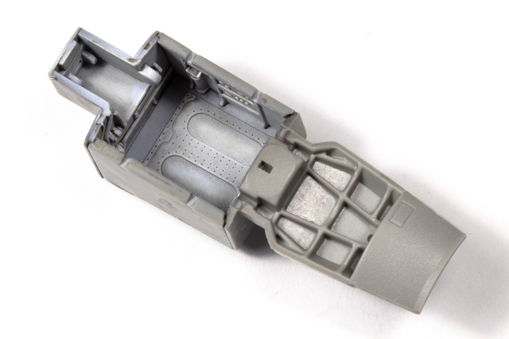
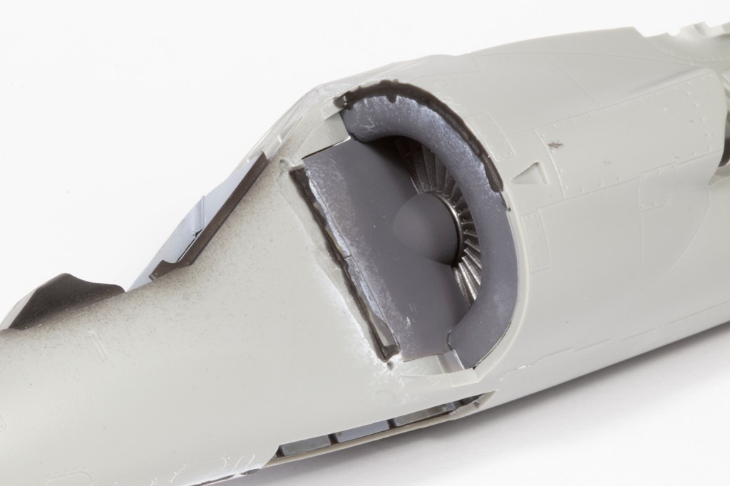
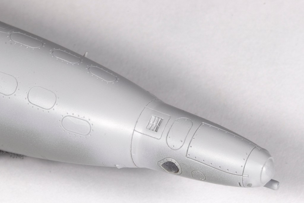
Finally, the intakes need to be addressed. This was more complicated than I anticipated. First, pay attention to the instructions and make sure the intake interiors are painted the correct colours (i.e., not white). I elected to add the intake fan part to the cockpit and then put the entire fuselage together. The fit was fairly good, but I had to use a lot of CA with filler powder and shims of plastic card around the rear gear bay doors. I also took the opportunity to remove the seam between the intake interior and the fuselage sides so no join would be visible later through the open blow-in doors.

My focus then switched to the front intake parts, made up of the outer shells, inner linings and the separately moulded section with the doors. There were way too many gaps for my liking, so quite a lot of time was spent closing them with filler and plastic card before patiently filing it all down with files.


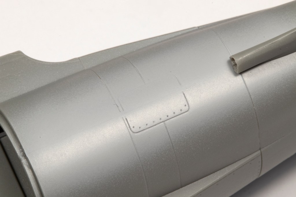
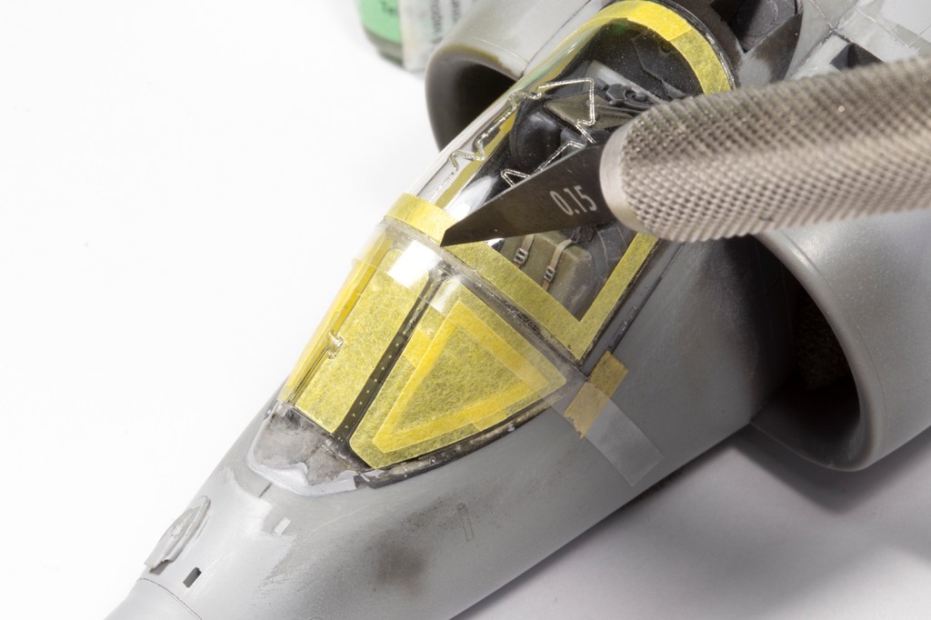
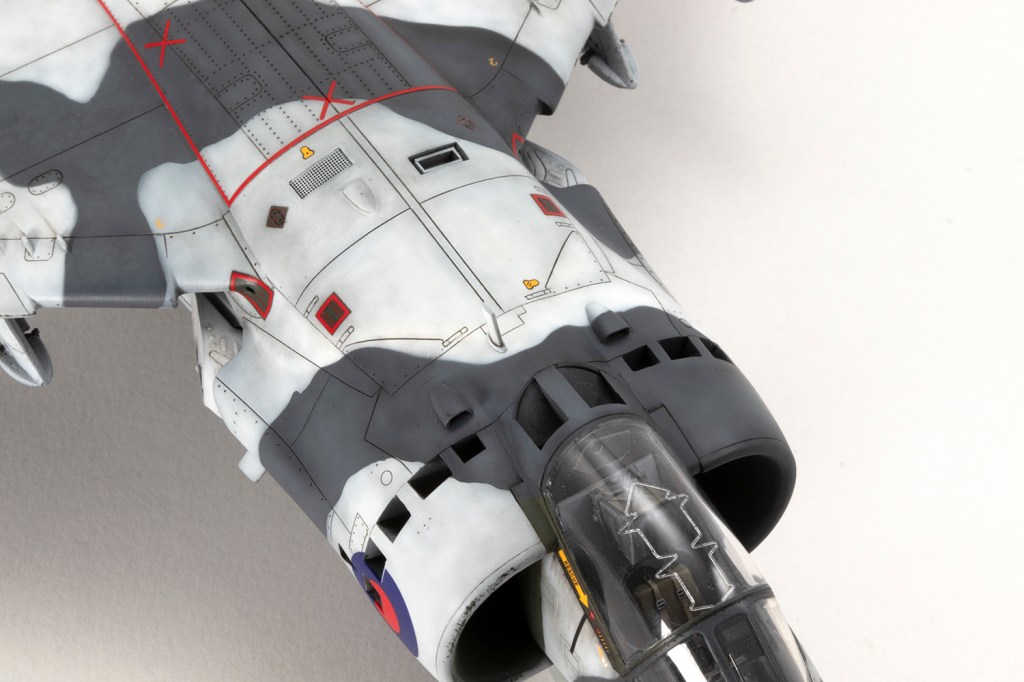
With the fuselage essentially complete, I needed to rescribe the panel lines near all the joints. My goal here, however unattainable it may seem, is to make the rescribed areas indistinguishable from the moulded detail. This is a difficult task which I’ve found easier by adopting the following method. With the joints all addressed, I primed the areas to be rescribed with a grey primer. This really allows me to see what I’m doing as restores the surface to a blank canvas and the rescribed lines will show up very clearly. Next, I needed to brace the model. My friend John Chung, who I consider to be the best ‘scriber’ I know of, advised nestling the model in an old T-shirt. I poo-pooed this for ages, but actually tried it on this model, and I think it’s a game-changer. The shirt allows the model to be stably rested in almost any orientation and frees both of my hands for the actual scribing. It’s critical to use the best guide for the scriber, which depends on the area. My preference is clear scribing tape, made by Madworks or HIQ Parts, which is excellent but doesn’t deform, so it can’t be used for curves or on parts with a taper, so my second choice is Tamiya Tape for Curves. Finally, I tend to use the Madworks DLC 0.1mm and 0.15mm scribers as I find them much easier to use than the multitude of other scribers I own. With all this I could scribe in the rear undercarriage doors and the panel lines around the fuselage that had been obliterated through sanding.


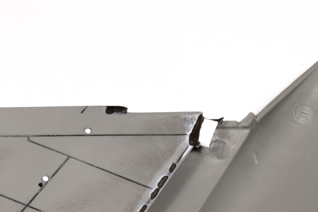
Back to the wing – there’s yet still more to battle against. Kinetic have moulded some protrusion to the front of the leading edge of the wing part, which the instructions tell you to remove. I understand that this feature should be retained on the finished model, so the SIG documentation advises you cut a notch in the fuselage section to accept it, rather than remove the part from the wing. I reckoned it easier to cut it off and then rescribe the shape later on.
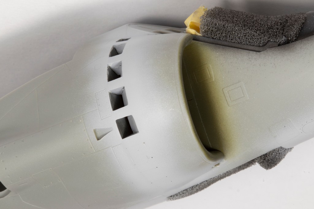
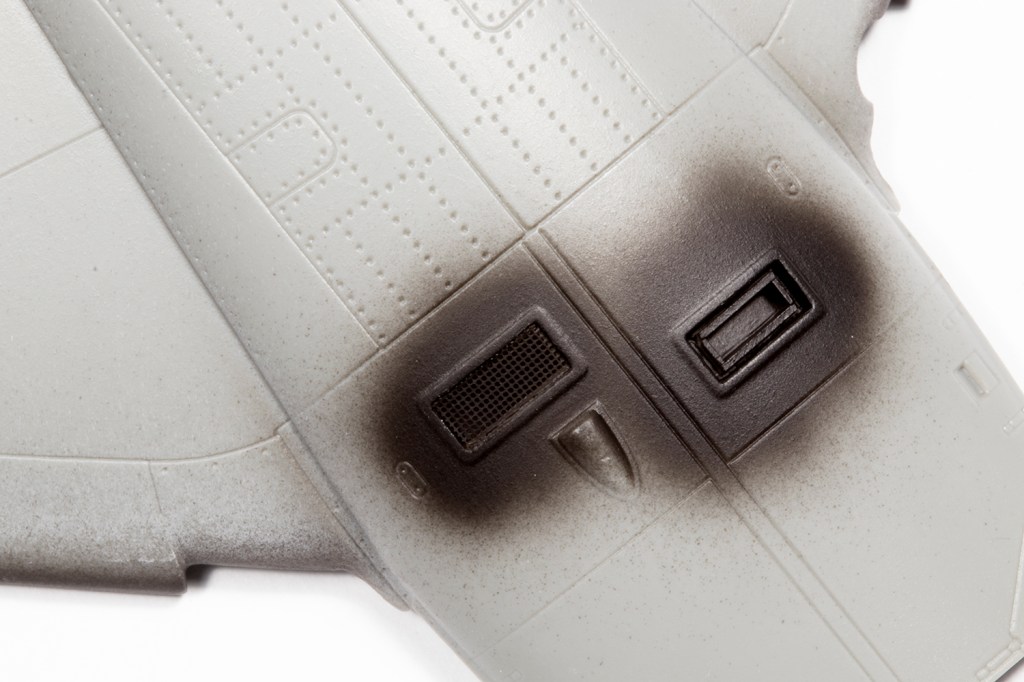
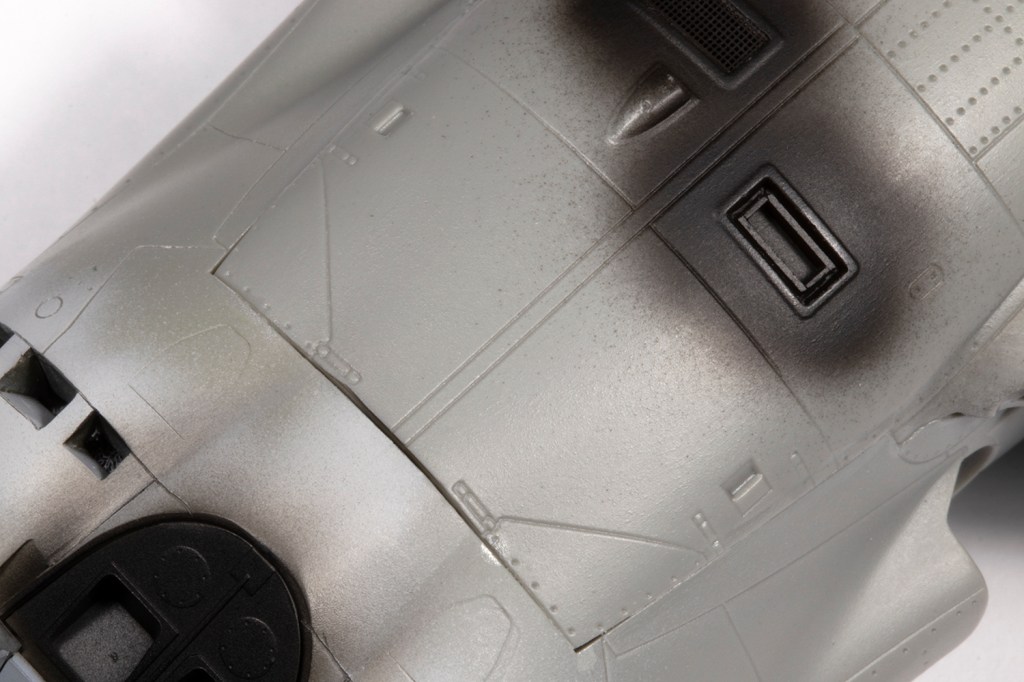
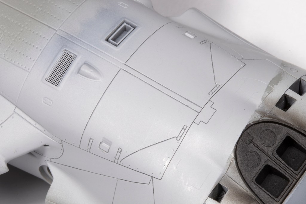
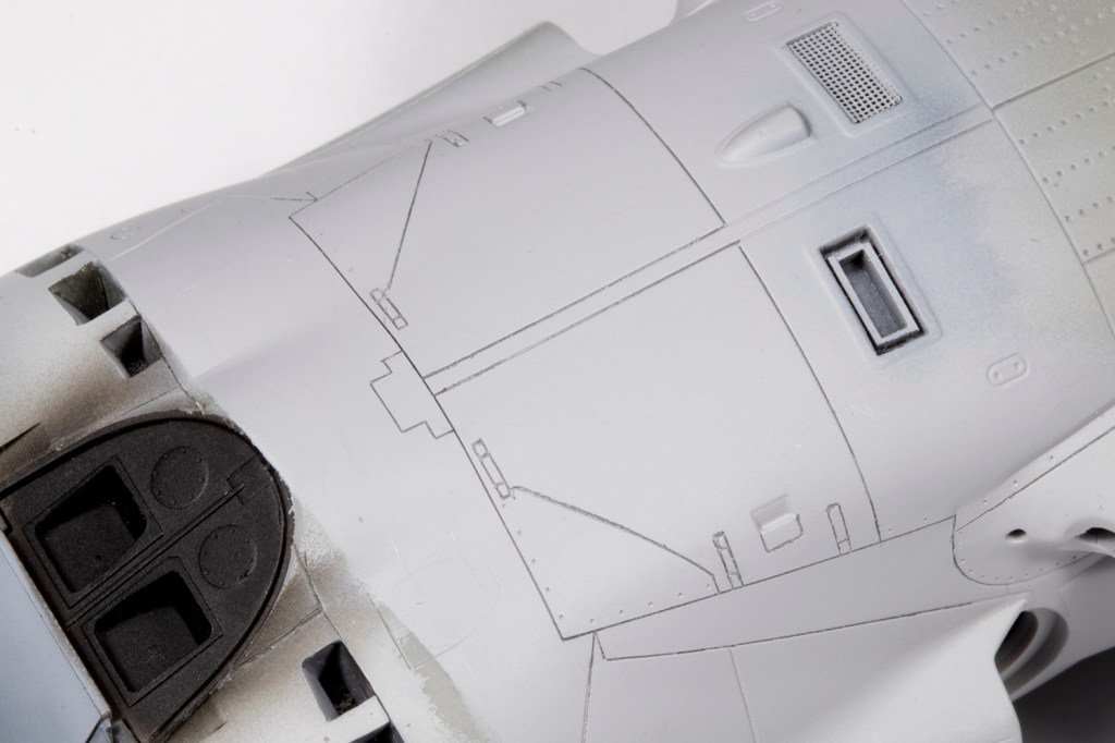
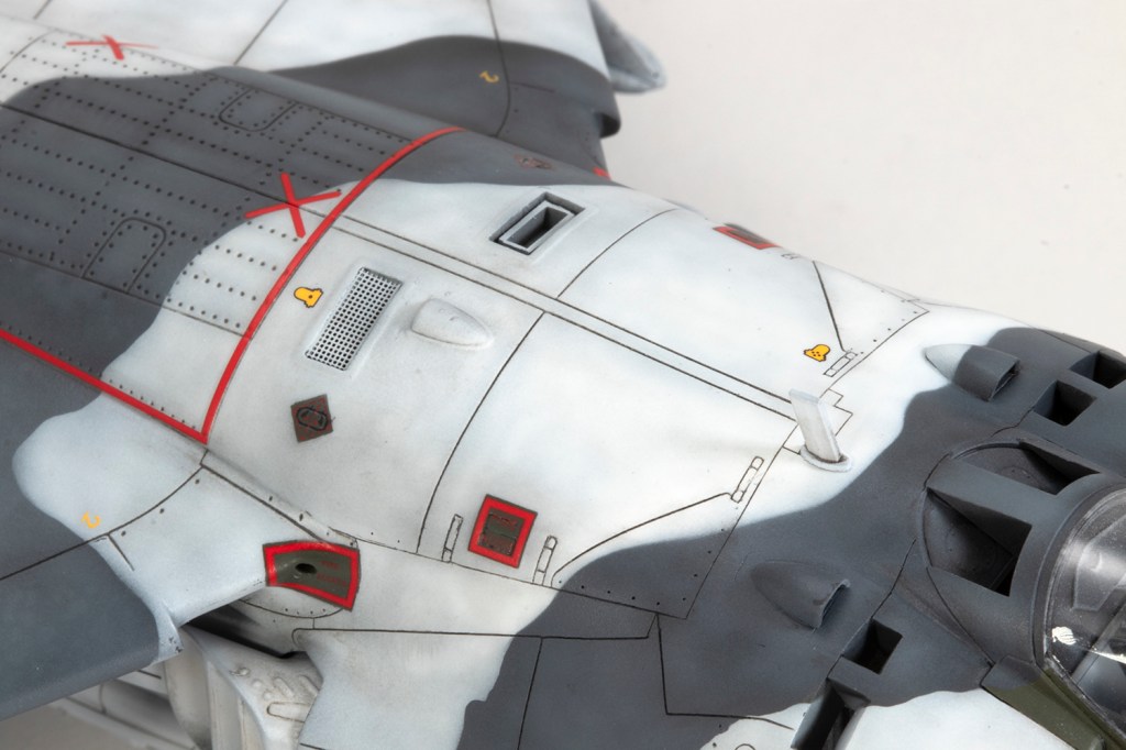
I also took the opportunity to cut away the moulded grille for the APU intake in the upper wing part and replace it with some generic Eduard etched PE mesh. The nearby APU exhaust is just moulded as a blank rectangle, which will not do, and thus I cut that away also and knocked up a rectangular vent to fill the void. This is ripe for replacement with a 3D printed part (hint hint).
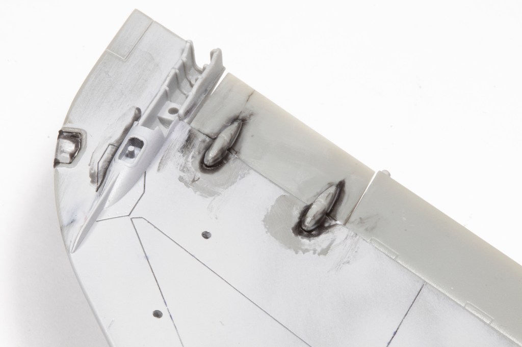
With that, I could attach the wing. Now, there are plenty of articles out there, including those previously published in this august publication, which offer methods to get the wing to fit well to the fuselage, but for the life of me I couldn’t get them to work. I had steps and gaps galore around both the front and the rear. I’m not a subtle modeller, and inevitably end up blasting on filler and asking questions later, which is exactly what I did here. On the underside, plastic card shims assisted with plugging the sizeable gaps.

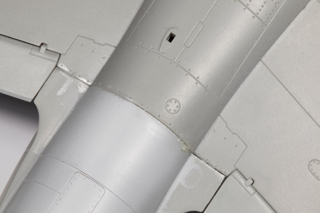


Once the filler had set, which with CA isn’t long, I could set to on it with lots of various sanding implements. I knew I’d end up eliminating quite a lot of the recessed detail, but with the method outlined above and VMS Black CA and Filler Powder used as the filler, I was confident I could rescribe it well enough. It took a couple of rounds of filler and sanding to get perfectly smooth transitions across the wing/fuselage joints, but it was easier than I feared.


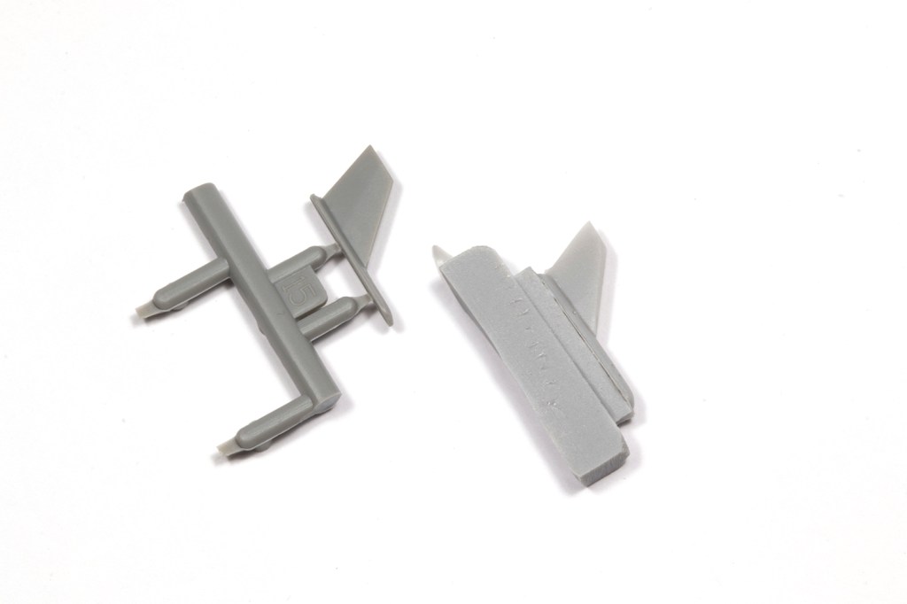
When it comes to the tail planes, Kinetic do the modeller no favours at all. They have significant anhedral, but there’s nothing in the kit to help you set it. There is a plate with a locating peg that flops around in an oversized hole in the side of the fuselage. You’re then meant to attach the actual tail plane to this plate and, when it comes to that anhedral, hope for the best. Although it went against my instincts, I decided I needed to attach the tail planes now, rather than at the end, to ensure the angles were all correct. My method was to glue to the tail plane to the plate, then glue the whole lot to the fuselage before the glue had set. With Tamiya Extra Thin the glue goes off quick enough I could just hold the part in place at the correct angle. When that was set, I could attack the opposite parts to match. It’s inexplicably difficult.
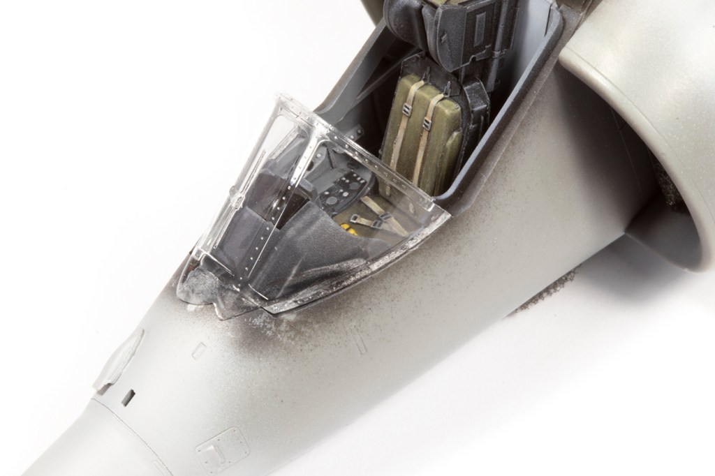
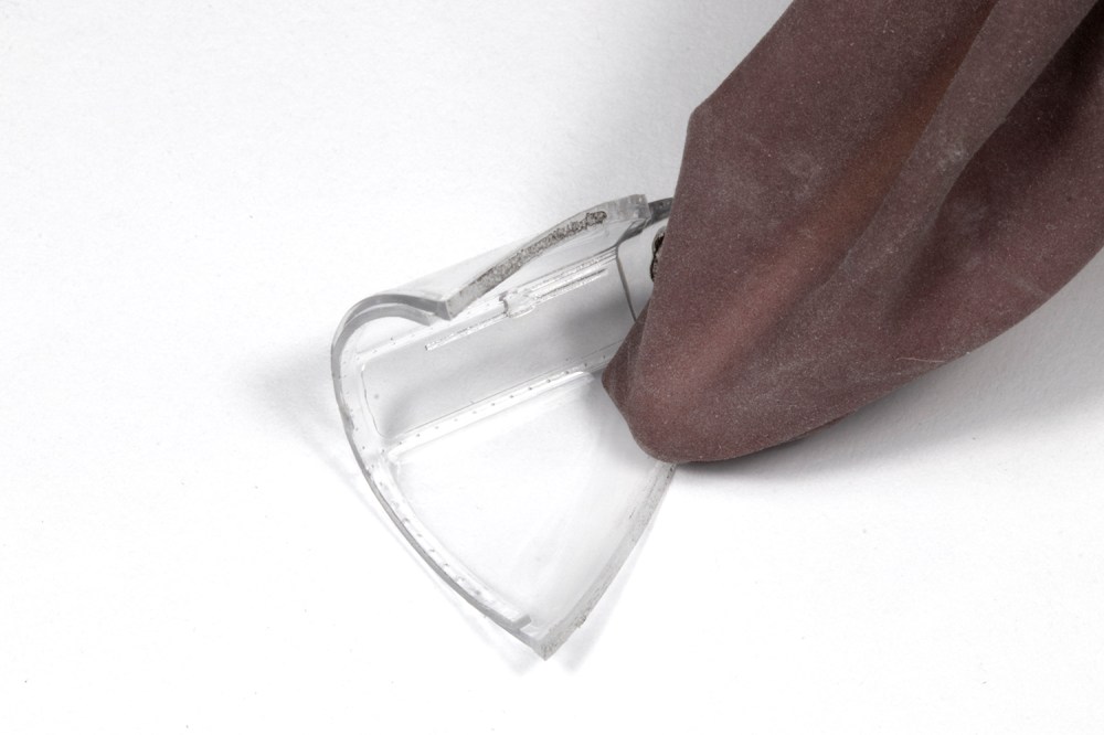
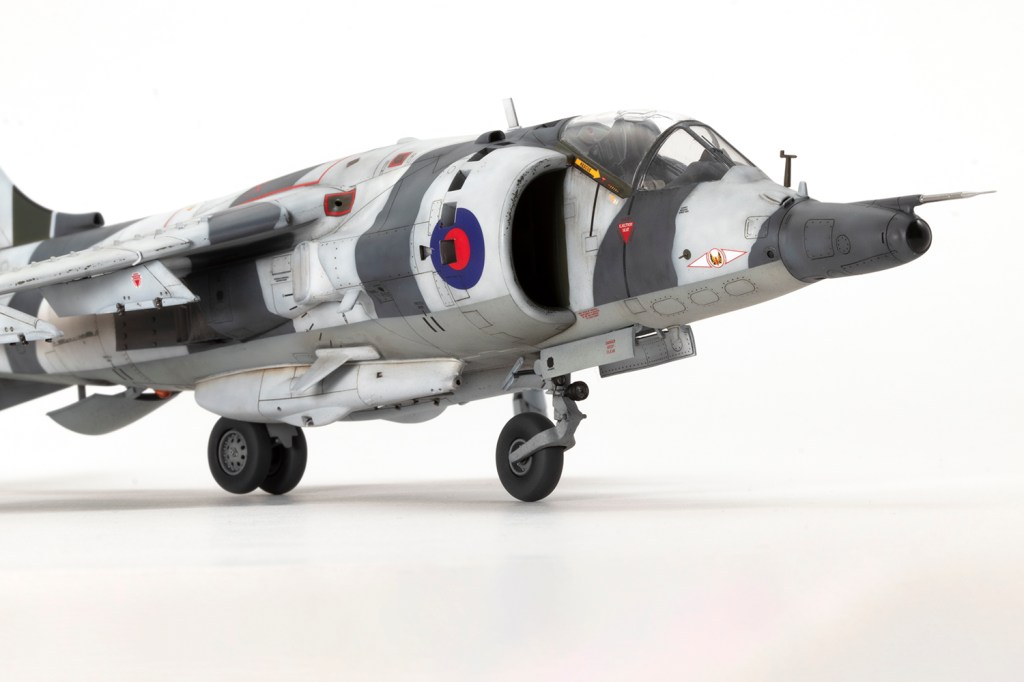
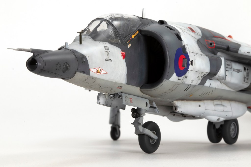
Final areas to deal with prior to paint were the canopy and guns. If you like your canopy open, you will rejoice at the wonderful fit of the parts. If, like me, you insist on canopies closed (aircraft look so much nicer this way!), you’ll curse Kinetic for getting it close, but not close enough. In order to prevent a gap between the main section and the fixed windscreen, I had to move the latter aft slightly, creating a gap at the front of the windscreen. This was filled with repeated applications of Mr Surfacer 500 and then all the joints removed with filler and the canopy shut lines scribed in. The main problem with modelling closed canopies is sealing the interior, and I failed to do so: very fine dust has contaminated the inside surfaces of the clear parts, and there’s nothing I can do about it… I used New Ware masks, which fitted very well.


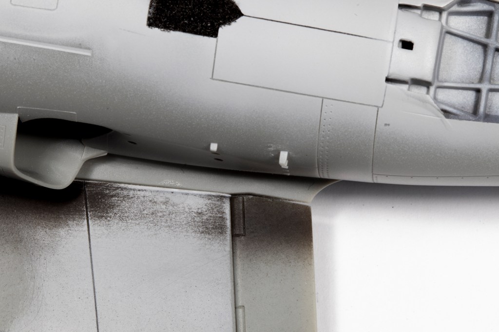
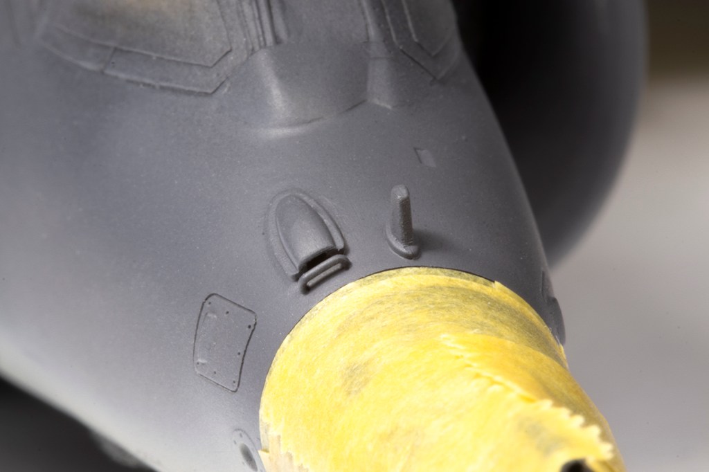
I was modelling an airframe from two photos, kindly supplied by the SIG, which showed the Aden gun pods fitted. Whilst they look very cool, they are also a pain, as they’re very simplified and Kinetic provide absolutely no guidance whatsoever on where they should be fitted, other than a not-terribly-helpful plan line drawing of the underneath. I used the Black Dog parts as a pattern for my own modifications to the kit guns, which mainly involved drilling quite a few holes, adding a few vents here and there, and putting in some brass tubing for gun barrels. What I did not attempt to add were the various bulges Kinetic missed off. With some trial and error, the pods were eventually cemented in place.

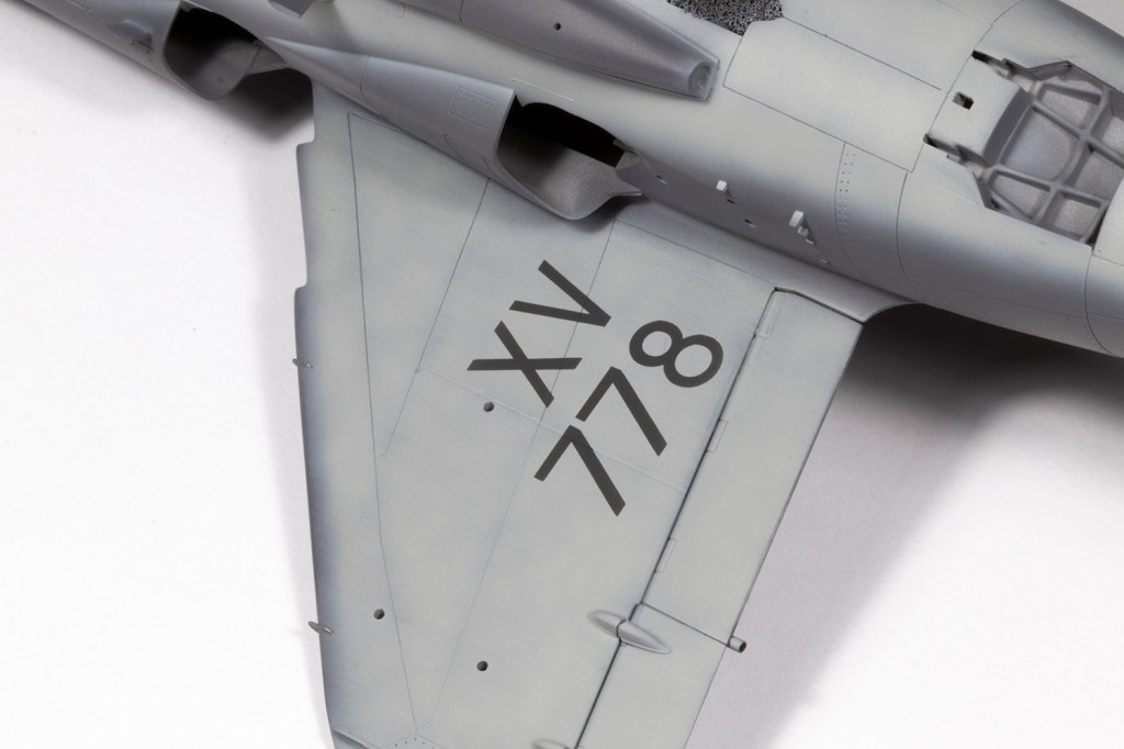
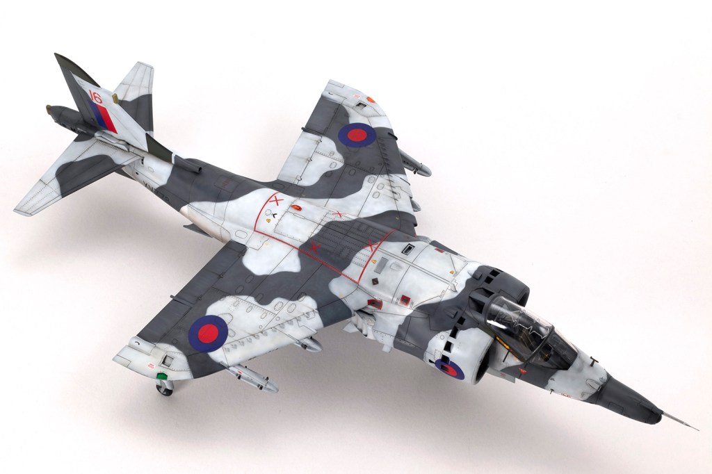
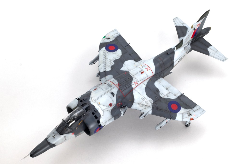
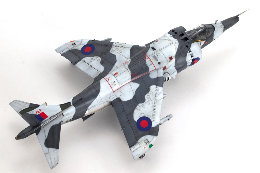
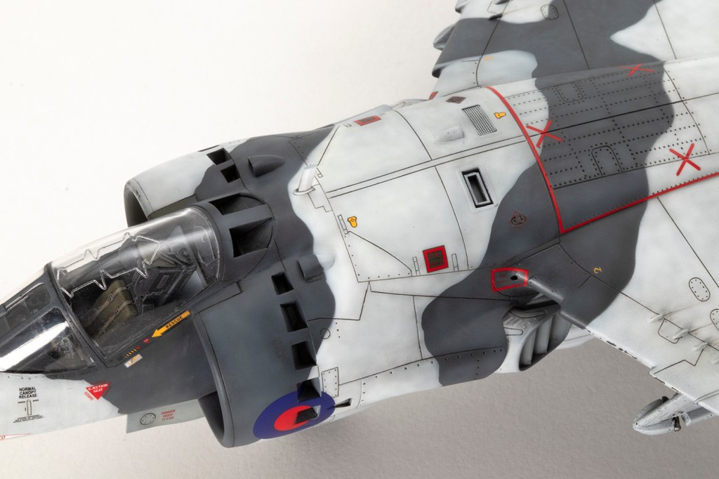
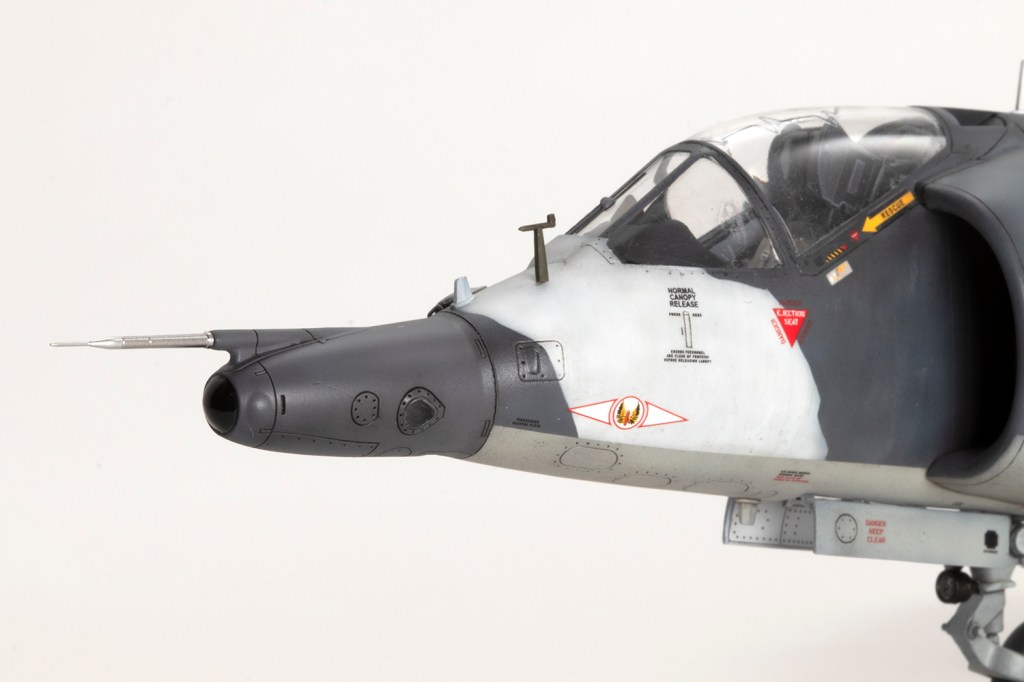
XV778 was photographed in Norway in March 1979 and I had a couple of the pictures, both of the right hand side. Arctic Harriers generally had the green sections of the camouflage overpainted in white, and the way this looked could vary dramatically from deployment to deployment. In this case the photos showed a finish on the neater end of the scale, with stencils and markings painted around rather carefully and the white paint looking rather tidy. Close examination of the photos reveals nice details, like the green canopy sides and nose entirely in Dark Sea Grey. This particular airframe retained the Light Aircraft Grey undersides with pylons, gun pods and the fuel dump all in white. I’m sure I’ve made errors (around the serials, for example, where I could not interpret the photos clearly), and the right hand side is guesswork.
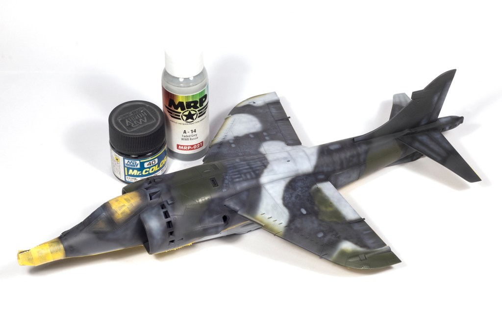
The paint is mainly Mr Color and MRP and the white/grey camouflage demarcation was achieved with thin rolls of Blu-Tack. Some areas were painted in Dark Green and then masked with masks I made from a scan of the decal sheet so that some of the stencils retained a green background. Markings are mainly from the kit sheet which is printed by Cartograf, and I have to say they were fantastic. My only criticism is that the red is a little translucent so some of the underlying camouflage is visible through the tail flash. I think the red and blue for the roundels is a bit bright, but it’s extremely close to that printed by Xtradecals and the advantage of the Kinetic roundels is that they are pre-cut for the open doors. Aside from the red ‘16’ on the tail, you could make this airframe with the decals in the kit. The quality of the Xtradecals was also top notch. Just because I like to do it, the serials under the wings were airbrushed through masks cut on a Silhouette cutter.


On recent projects I’ve been experimenting with sanding over the decals to reduce the evidence of the decal film. People generally recommend Alclad Aqua Gloss for this, but since that (or the Ammo branded version) are unavailable in the UK, I tried Tamiya X-22 Clear. After airbrushing it liberally over all the decals and allowing 36 hours to cure, I sanded over them with small pads of Infini 1500 grit sanding sponge. I should probably have used the 2500 grit as the scratches were a little difficult to cover later on. This worked okay, but you have to go super slow – I sanded through the paint in a couple of small areas, which needed touching up. I do think it unifies the decals better into the final finish though. But please, can someone bring Aqua Gloss back to England?
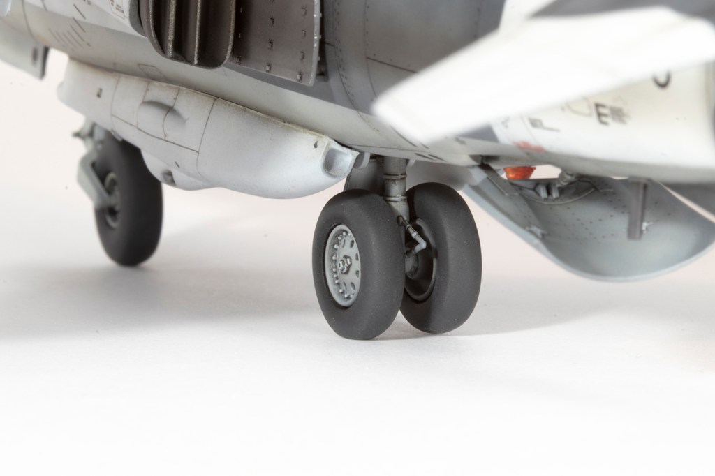
A final word on the undercarriage. The challenge with any harrier is to get all five wheels on the ground. The best way to do this is to leave the rear main gear loose so it can move up or down to match the front and the outriggers. I duly did this, cutting away the awkward locating pegs and using a brass wire to allow the leg to move up and down. What I did not account for is that Kinetic did not mould the holes for the rear leg axle centrally, so my wheels sit at slightly different heights on the axle and thus one floats off the ground whilst the other is firmly planted. This is ultra-annoying and next time I shall try using some aftermarket wheels to see if they improve the situation.
My last tip is to check the airbrake fits properly much earlier in the build. I didn’t, and I had to push the arms quite firmly into the slots. This fractured the plastic around the slots, right across the undercarriage doors. A lesson learned for next time, when I make the FA.2, T.2 and AV-8A.
To be frank, the Kinetic Harrier is a bit of a disappointment, and is not what I would expect from a major kit manufacturer five years ago. Lots of modellers seem to have had no trouble building theirs, but my experience was different. Having said that, it’s regarded as quite accurate, has superb decals and can be made into a nice model. I’ve got another three more in the stash, and my desire to make them is undiminished. Particular thanks to Nick Greenall from the Harrier SIG for the encouragement and information; all errors and inaccuracies remain my own.
UPDATE: After I wrote all the above and photographed the model, I did go back and fix the main landing gear. The explanation is in the captions:


Year bought: 2020 (Lucky Model)
Year built: 2025 (New Addington, Croydon)
Back to home.
