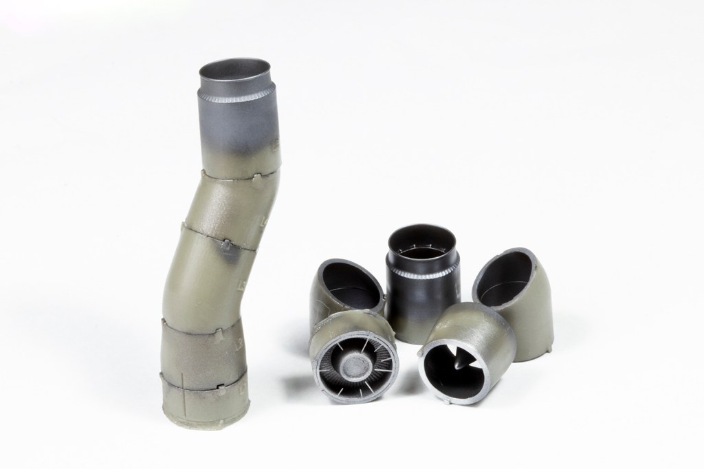
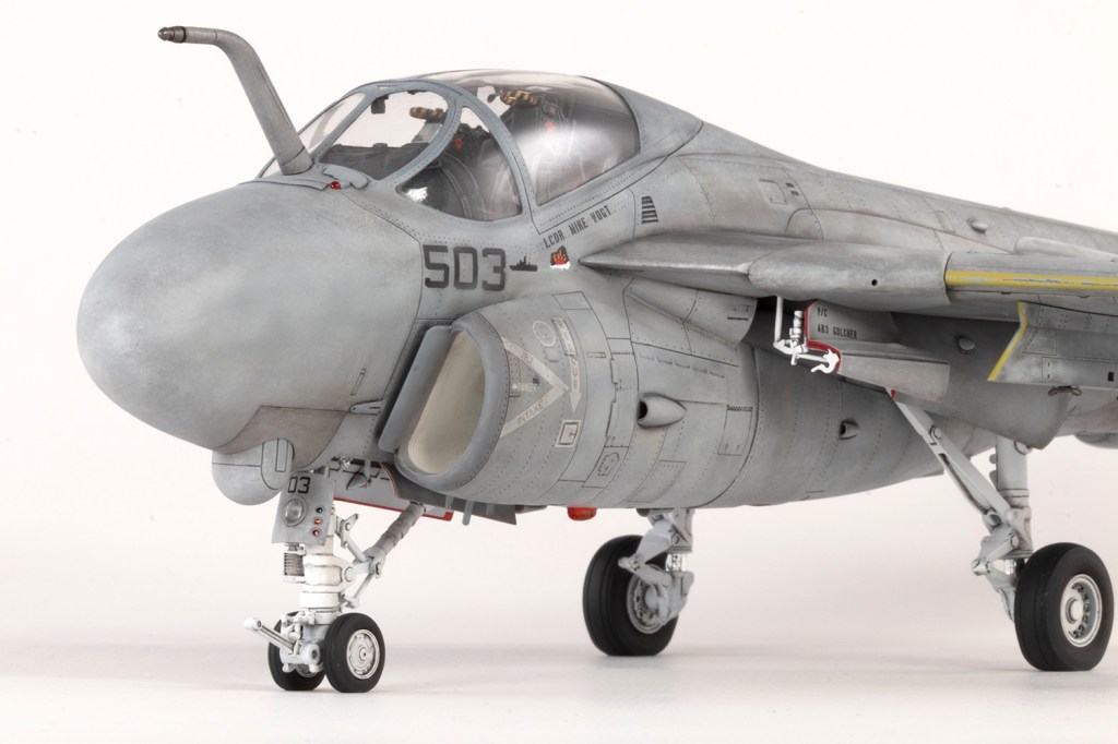
with AOA Decals decals, Hypersonic resin exhausts and fin tip, Master metal pitot and ResKit resin wheels
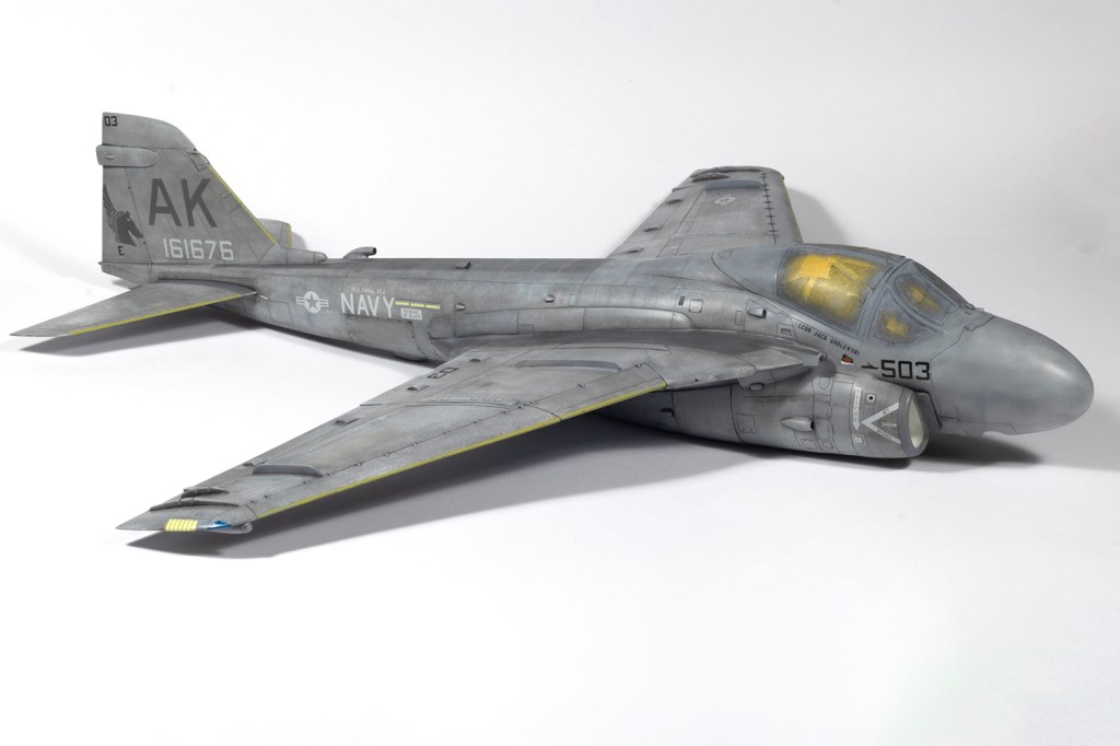
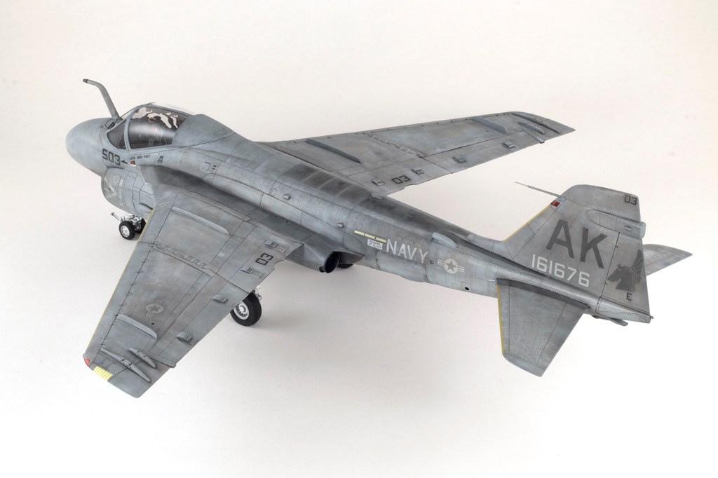
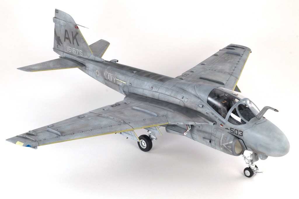
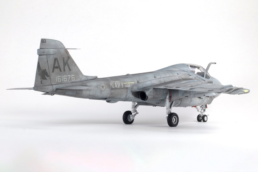
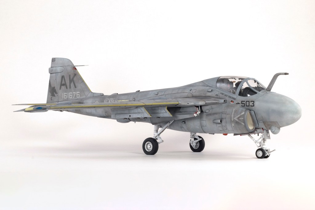
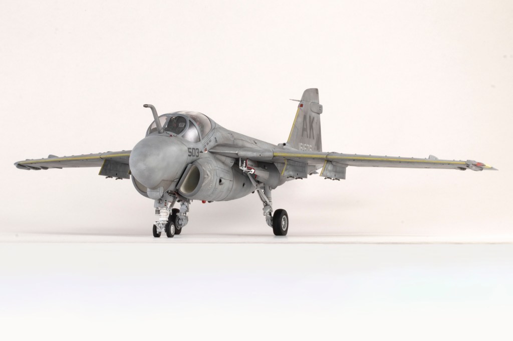
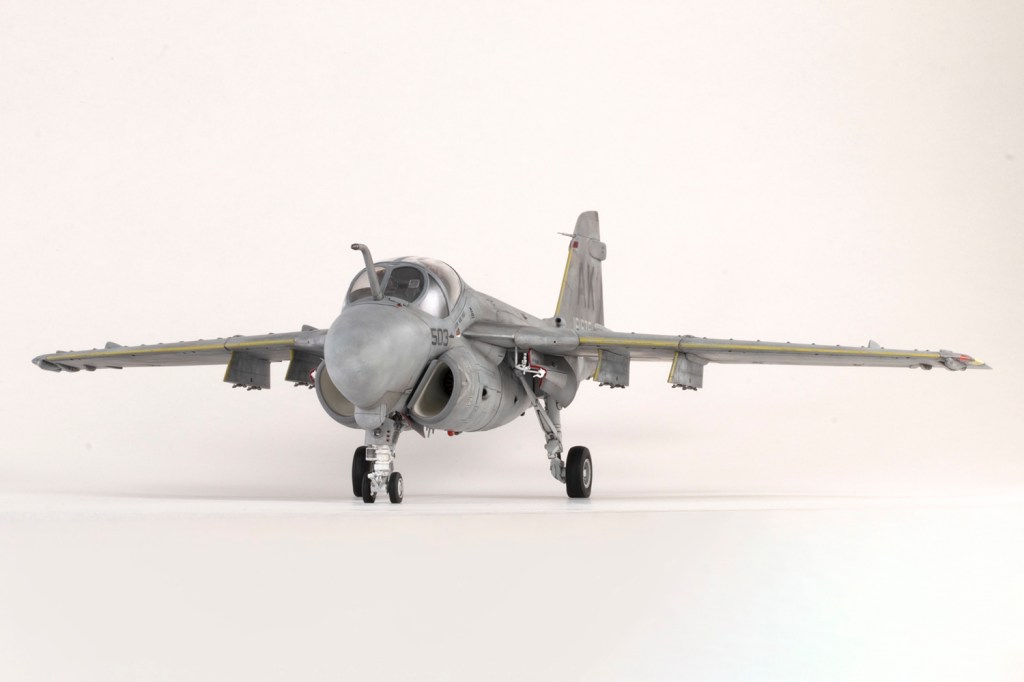
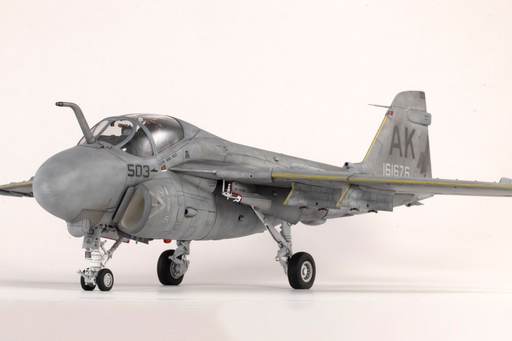
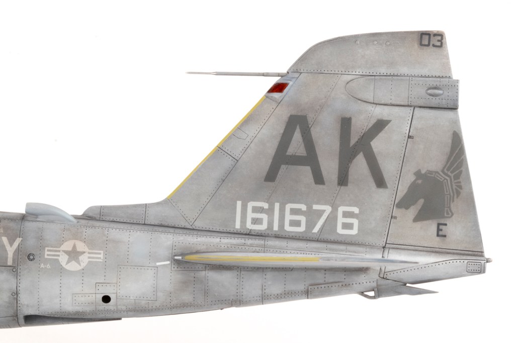
VA-55 ‘War Horses’, US Navy, USS Coral Sea 1986

This project started out as a Revell 1/48 A-6E, purchased way back when in 2003 when the tooling was 15 years old and it was the only kid on the block for subject and scale. I even got most of it rescribed and completed the cockpit, but always with half an eye on the much newer Hobby Boss kit. After all, 1988 is a long time ago and things have moved on. If it were to sit alongside my Hobby Boss A-6A, the Revell kit would have looked clunky, and in reality it’s not very nicely moulded or engineered. After slathering it in superglue filler and playing with all the major parts, I succumbed to the dark side and for the first time since 1994, abandoned a started kit.
I immediately found a cheap Hobby Boss A-6E on eBay and purchased the Hypersonic upgrade parts I already had lined up for my A-6A: a resin fin tip, which corrected the kit’s shape, and some resin exhausts which are beautiful, but largely invisible. Decals would be from AOA for a line jet in the TPS scheme which took part in Operation El Dorado Canyon and bombed Libya in 1986.
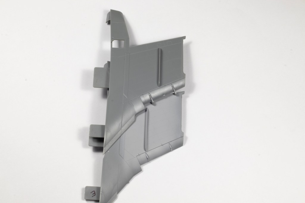
The Hobby Boss A-6E TRAM boxing takes care of a lot of the changes from the A-6A, but not all of them. Distinguishing A-6 variants is not easy, and alterations were made without a change in designation for both the A and the E. My guides to the necessary alterations would be Tommy Thomason via his peerless ‘Tailspin Topics’ blog, and the AOA instructions. When I opened the box, I was unreasonably happy to find that the leading edges of the inner wings were correctly shaped for the E; I had assumed that since they shared part numbers with the A model that I would have to scratch build these.
There are a lot of parts in the box, even after all the ordnance was immediately consigned to the spares bin. Hobby Boss have moulded every control surface separately and deployable, including the wingtip airbrakes, as well as folding wings and a nose that can be opened to display a complete radar. The moulding quality is generally good (slightly better than the earlier A boxing, in fact), but does have some weak areas: inconsistent surface smoothness and scratches on some sections of the fuselage halves, some mould slip which is a pain to clean away, very rough intake splitter plates and a bit of flash and surprisingly chunky sprue gates.
What delighted me with this build was just how much could be done in parallel. Many model aircraft are quite linear to construct: start with the cockpit, then everything that needs to be sandwiched between the fuselage halves, join the halves, move to the wings, and so on. With the A-6 the build sequence needs to be quite different and many sections could be worked on simultaneously.
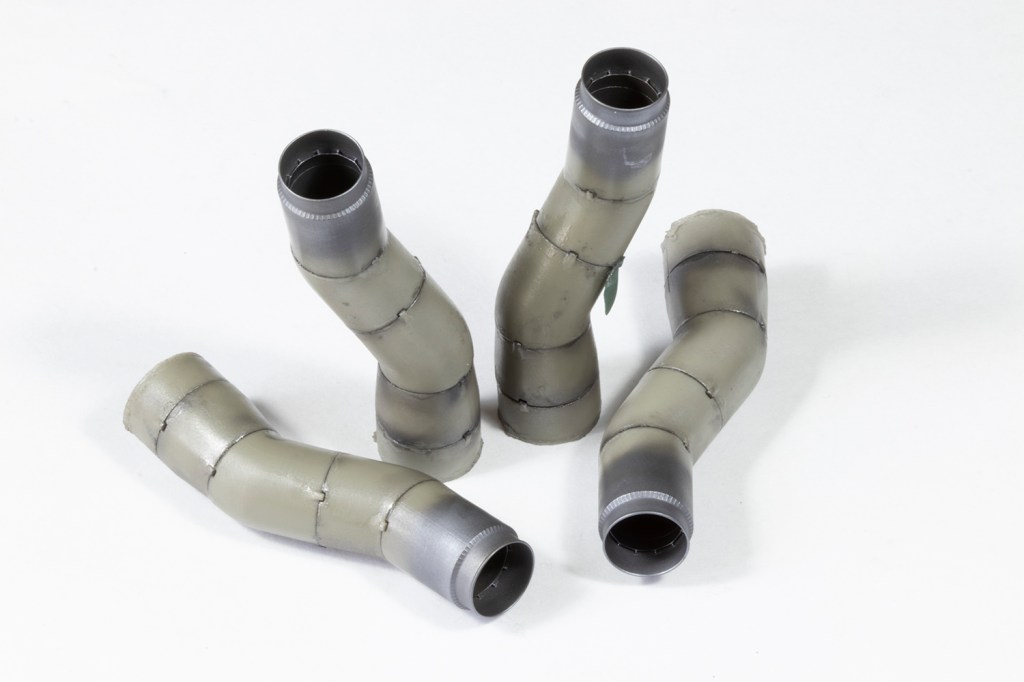
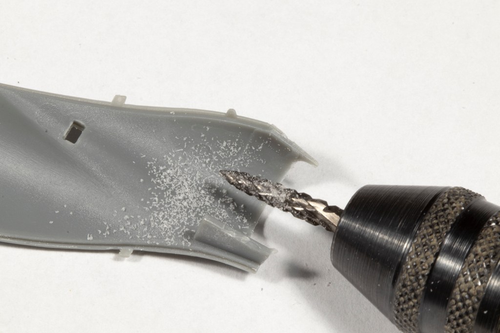
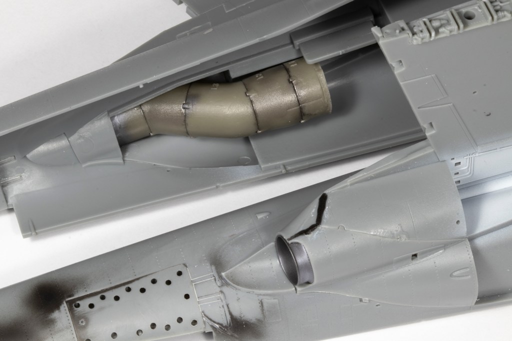
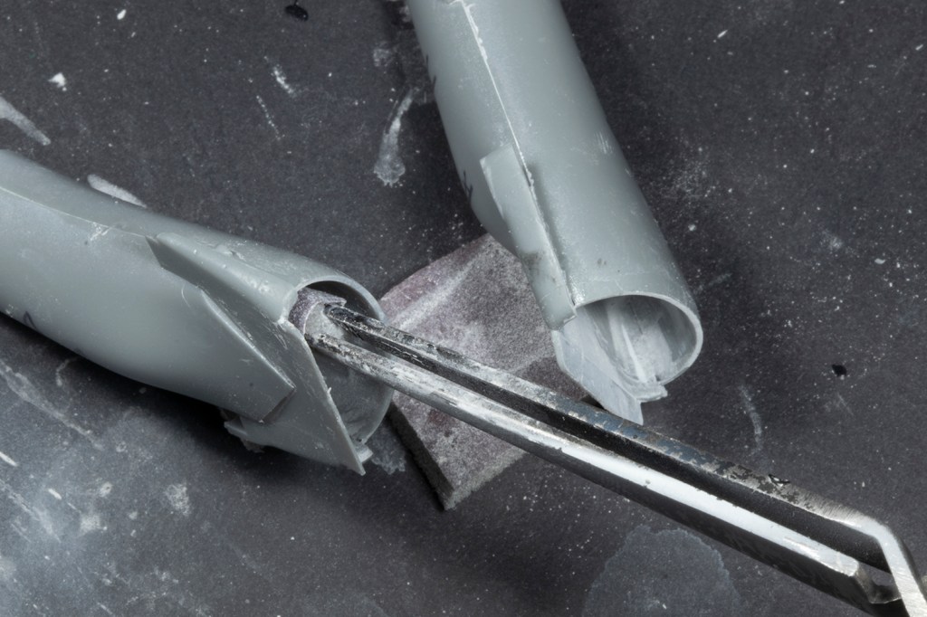
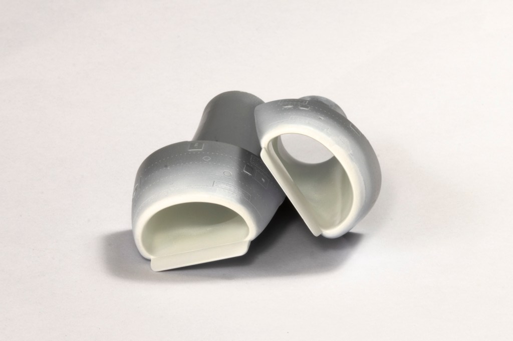
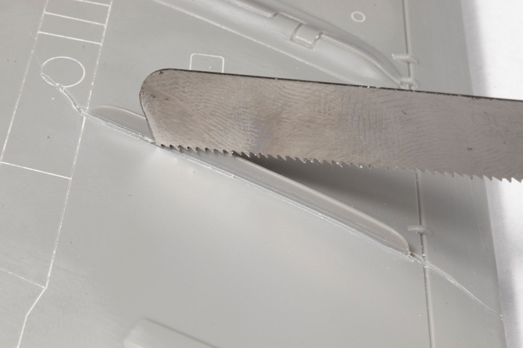
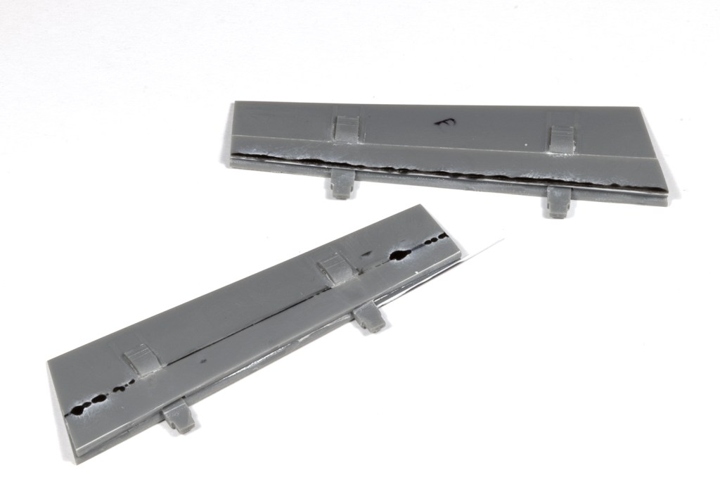
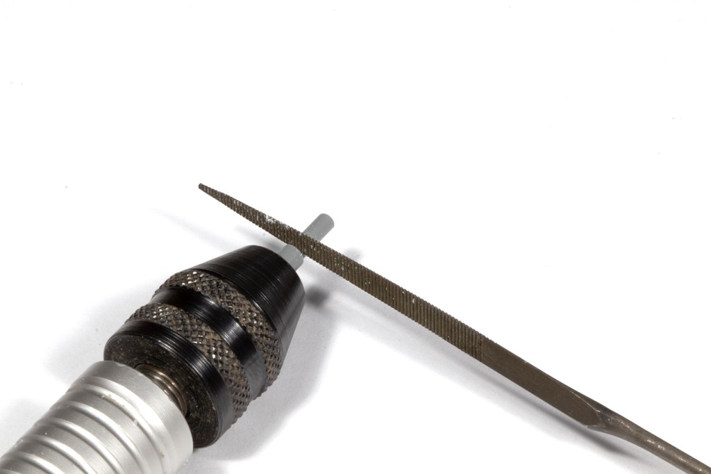
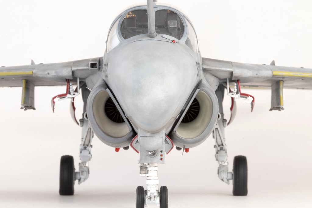
For example, I elected to replace the kit exhausts with resin replacements from Hypersonic Models. The kit exhausts are actually fine, but the internal geometry is over-simplified. The Hypersonic parts are mind-blowingly complete and provide a full trunking with complex detail at the end of the engine that could never be seen on the finished model. I absolutely loved this upgrade, but it does necessitate installing the inner wings before closing the fuselage halves. Fitting the resin exhausts requires thinning the kit parts and I used a DISPIAE grinding bit in my Proxxon motor tool to make this quicker. The danger is you might be as poor at controlling this as I am, and find it runs away from you at the edge of parts causing damage that needs to be fixed later… Once thinned properly, and with an awful lot of dry fitting, the Hypersonic exhausts slot in very nicely.


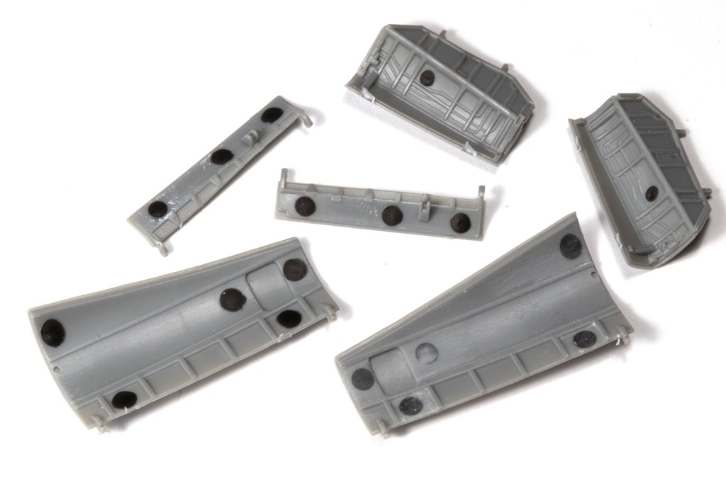
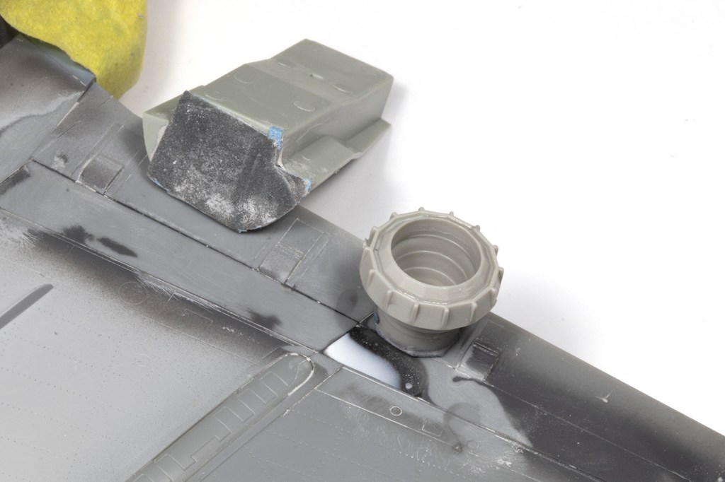
The intakes also need to be added before the fuselage halves are closed, and I’m a sucker for making these seamless. This is a lengthy and iterative process requiring CA and filler powder to first eliminate the ejector pin marks, followed by assembling the intakes and using more CA and filler powder to fill the gaps. Inevitably, after sanding, the first application is revealed to be inadequate, and a second round required. Then it all needs to be painted white, which is difficult down the length of a long tube. In this instance I used Mr Basic White 1000 sprayed very generously so it could be sanded down later with fine grit Infini sanding sponge to get a smooth inner surface.


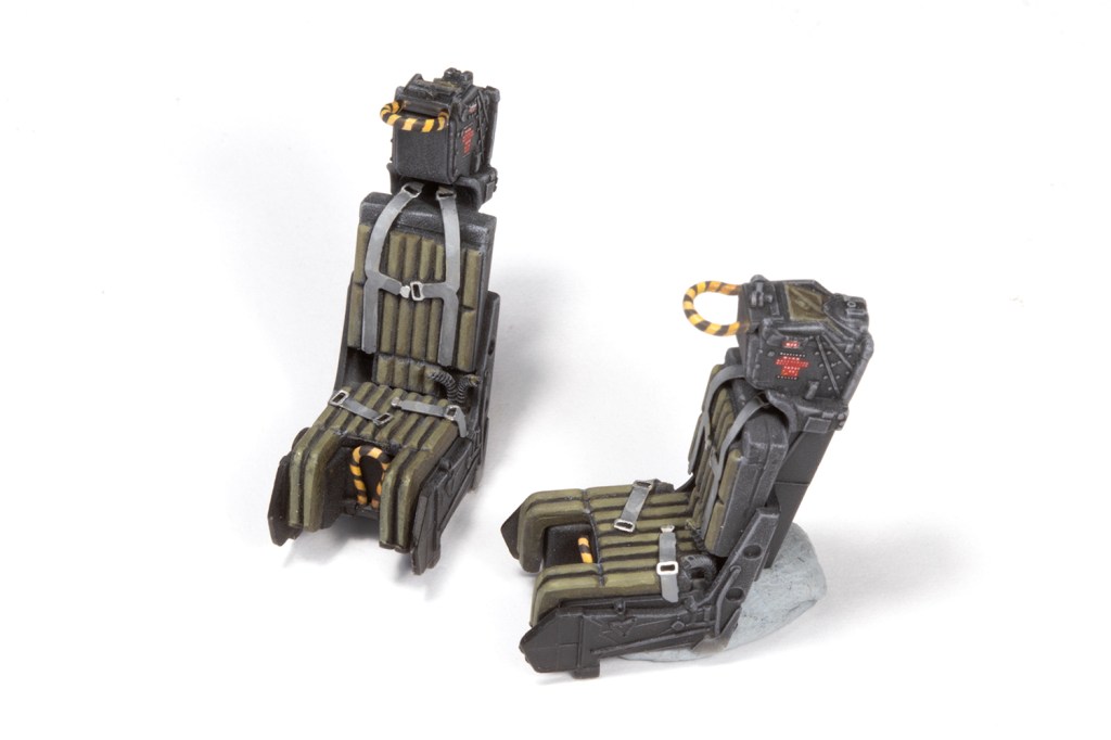
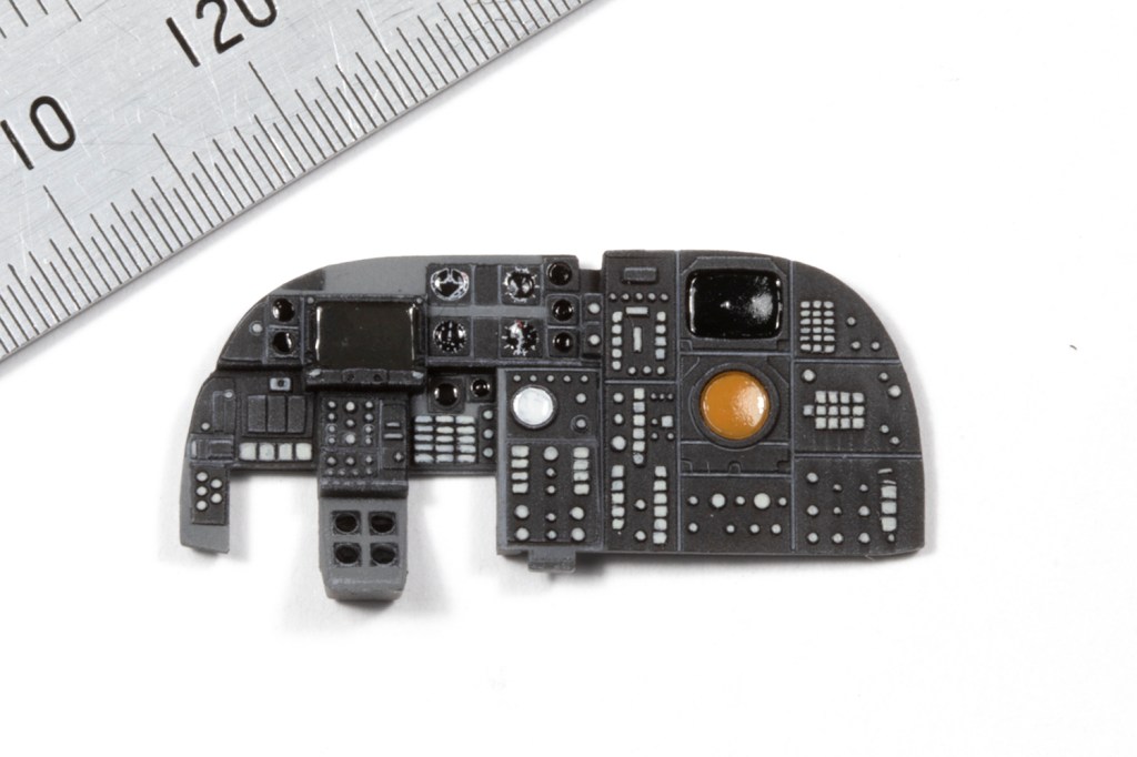
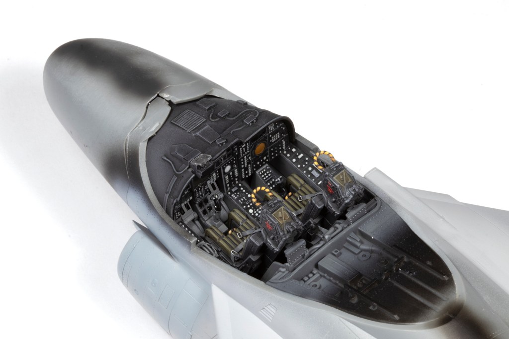
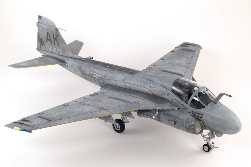
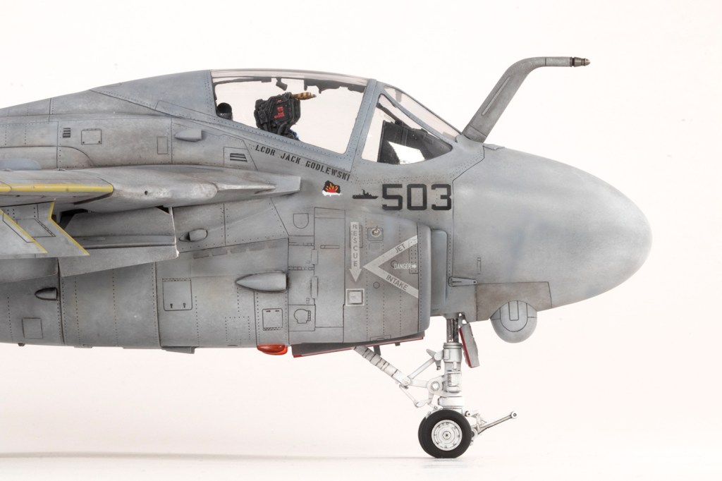
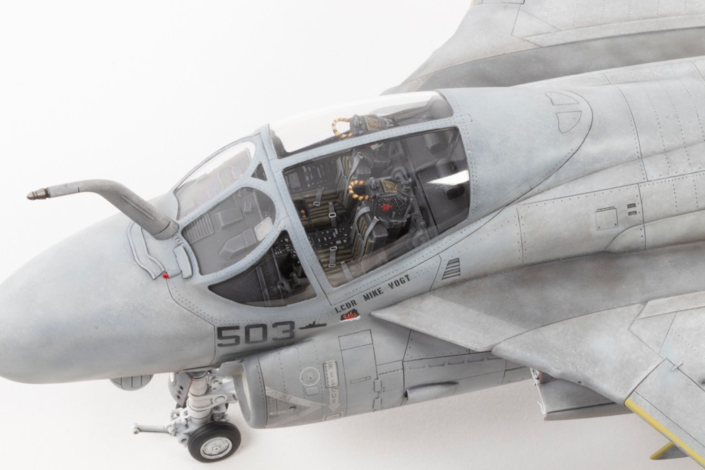
While all this is going on, the cockpit can be started. Since I was closing the canopy, I was satisfied with the kit details and seats and simply painted it all as neatly as I could. In fact, what Hobby Boss provide is excellent, and the seats rival plenty of resin alternatives. Photo etched seat belts are included as standard, and these are a weak part of the kit since they make very little sense and bear little resemblance to reality. I used them anyway.
The cockpit basics are airbrushed and then the panel details all painstakingly picked out by brush with acrylic paint – magnification essential. I added a few Airscale instrument decals, but even the smallest I had were too big for most of the dials. The seat cushions were also brush painted with various Lifecolor shades of Olive Drab.
I like to dry brush the black areas with oil paints, mixed to increasingly lighter shades of grey from black and white. After each application I airbrush a coat of MRP Flat Clear to lock the oils in place before dry brushing the next layer. I accept this isn’t terribly realistic, but I think it looks cool. With the ejection handles on the seats I tried masking the black stripes with 0.4mm strips of Tamiya tape. This works okay, but 0.4mm is still too wide and next time I’ll try using finer strips.


Concurrent with the exhausts, intakes and cockpit, I also attended to the myriad corrections necessary to make an accurate A-6E TRAM from 1986. Most of these were helpfully pointed out by the AOA Decals instructions, but I also urge the reader to visit Tommy Thomason’s Tailspin Topics blog at https://tailspintopics.blogspot.com/, which contains a wealth of useful information to model your chosen A-6 accurately.
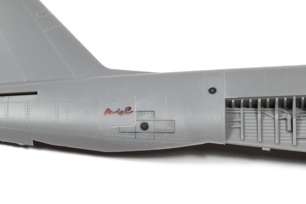
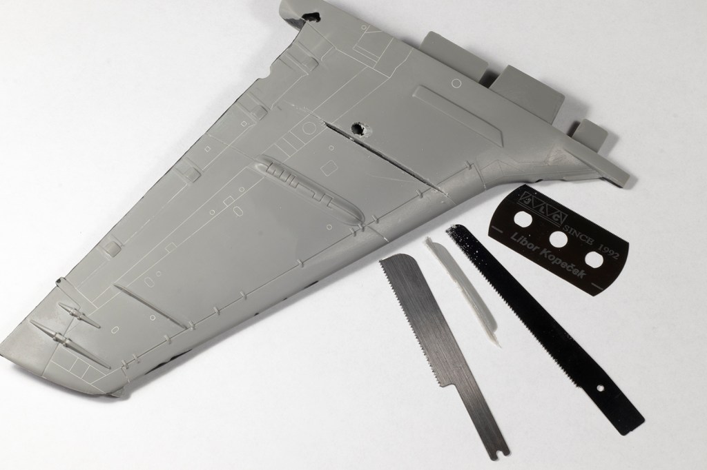
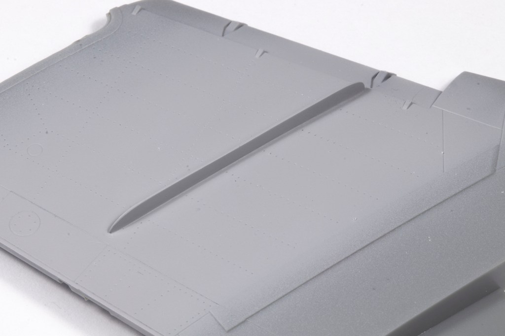
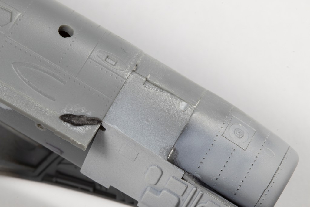
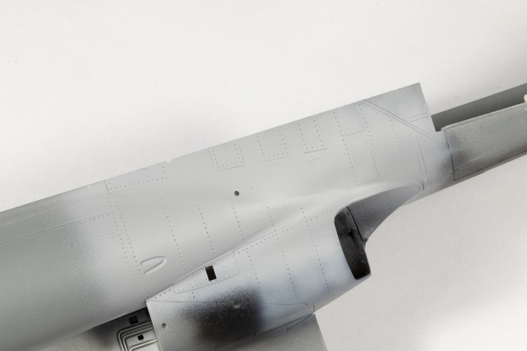
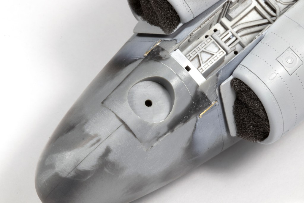
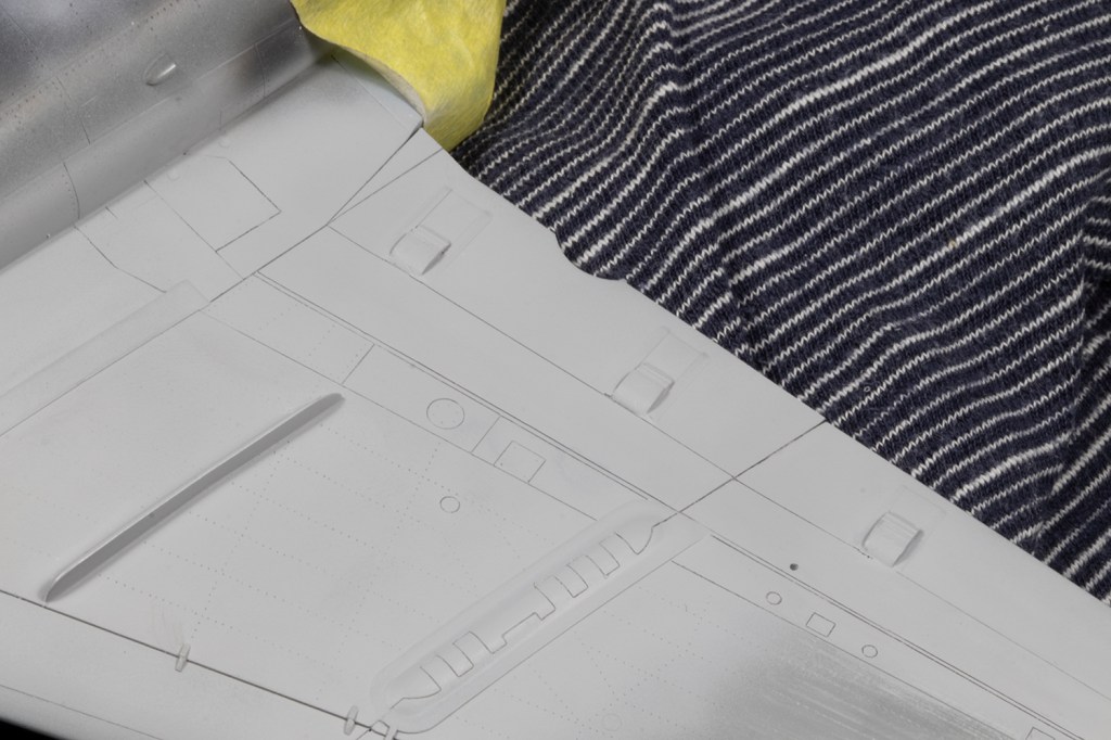
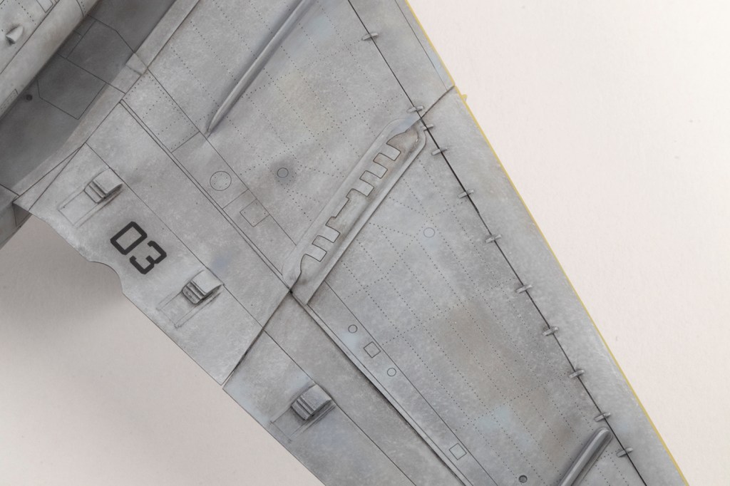
The first step was to use a black CA and filler powder mix to fill some surface details not applicable to this model: the vent exhaust hole and surrounding panel lines behind the airbrake on the right side. ECM parts for the trailing edges of the wings (L17/18) were not required for this airframe, and similarly the DECM ALQ-100 booms can be cut away from the inner pylon leading edges and the gaps filled. The biggest change, however, were the wing fences.
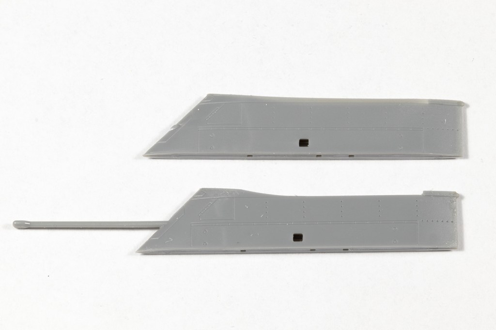
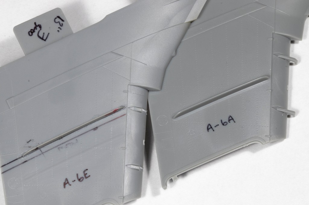
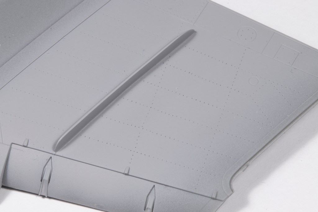
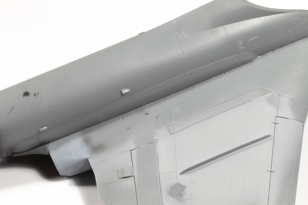
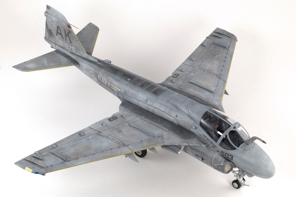
I couldn’t find this referenced in any book on the A-6 that I had, and was only alerted to the change by Mr Thomason’s blog. Once you start looking at photos of Intruders though, you can’t miss it. Essentially A-6As had the inner wing fence outboard of the inner pylon, but A-6Es had this wing fence inboard of the pylon. The change may not exactly have coincided with the introduction of the E model, so it’s worth checking your references. What I knew was that the kit was definitely wrong for what I was doing (as is the Revell kit also).
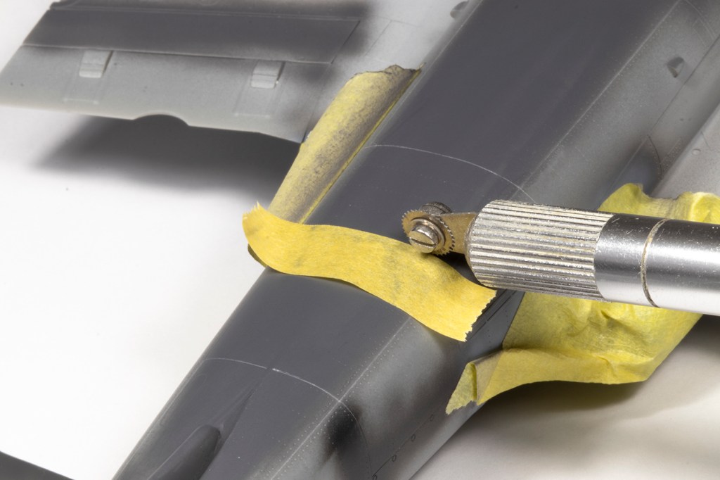
Initially I was reluctant to make the change. It would be very finnicky to get a decent looking result and clearly almost no one knows about this inaccuracy, but in the end I gave in and decided to move the inner wing fences. They should be 7mm (give or take) closer inboard. Rather than try and remove and reuse the moulded inner wing fence, I decided to hack it out from my discarded Revell kit. This took a while as the plastic is very thick, but allowed me to simply cut away the Hobby Boss fence from the wing without having to save it. The Revell fence was not quite the right profile to fit the wing, so I stuck down some Infini self-adhesive 400 grit sanding paper to the wing and gently massaged the Revell fence over the top of it using some locking tweezers. Eventually I had a new inner wing fence that fitted nicely and could be glued down. Where the old fence had been removed I restored the rivet detail with a 0.75mm rivet wheel from RB Productions. Truth be told, the kit doesn’t need rivets and would be better without them, but filling and sanding them all down looked too tedious.


Even without this work, the wings will absorb a lot of your time. With everything closed up, I counted 24 parts per wing, plus the optional sensor housings. That’s a lot of parts! If you want an easy life, I recommend modelling the flaps and slats all open and the wings folded. My sense of aesthetics drove me to want all the control surfaces neutral, and that made for a hard life. None of them fit particularly well and it takes a lot of fettling of various hinges, strips of plastic card added here and there, and many applications of superglue filler before the wings even started to look acceptable to my eyes.
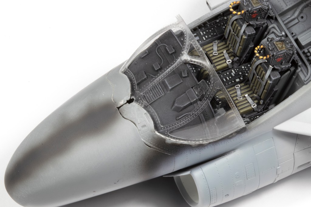
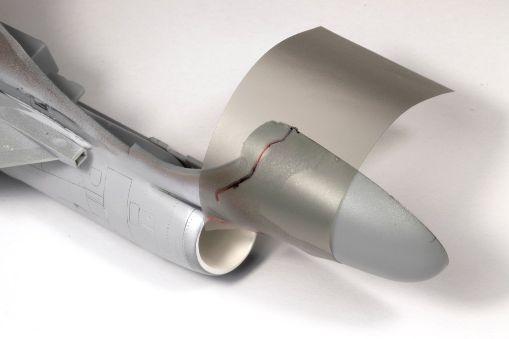
When it came to the nose I ignored the instructions and joined each half to its respective fuselage to try and get as good a join as possible. The mating surfaces are very thin and some plastic strip reinforcement on the inside was required. The nose (as with almost everything else) is clearly designed to be modelled open. I’ve no idea if nose weight is required, so I added some to be safe. A very long way into the project, the fuselage halves were finally closed.


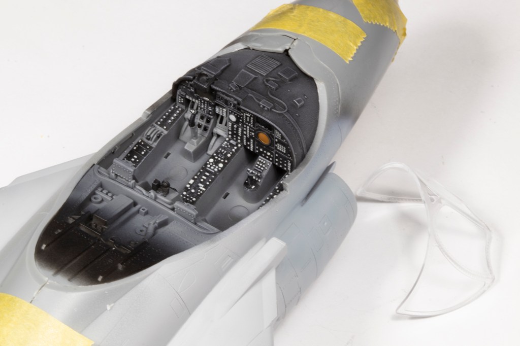

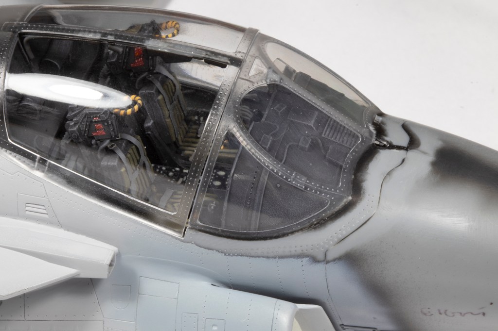
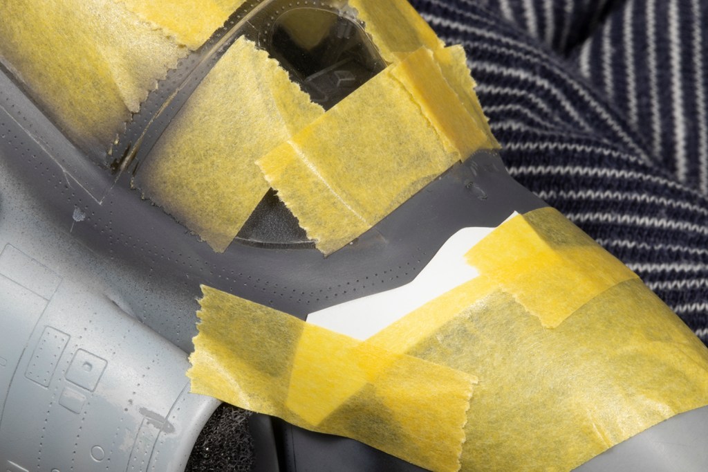
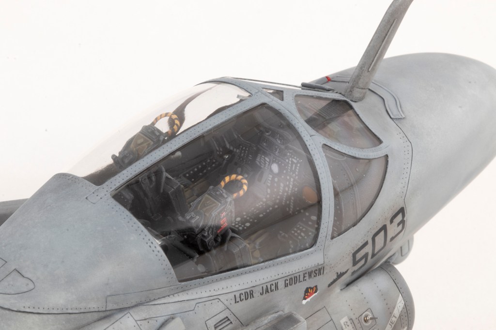
Ordinarily I like to get as much of the fuselage together as possible before adding the seat(s) and closing the canopy. However, because you have to add the instrument panel coaming before joining the fuselage halves, this left a lot of the cockpit exposed to potential damage when addressing the fuselage seams. I therefore finished the cockpit and added the clear parts much earlier than normal. The latter fit okay, except around the front of the windscreen where I was very glad I’d left the narrow strip of fuselage unglued across the fuselage join. This allowed me to flex the area ahead of the windscreen so I could actually get it to fit, and then build up multiple layers of black CA and VMS filler powder to treat the enormous gaps. To help prevent fogging from the superglue, I had coated the inner surfaces of the clear parts with Johnsons Klear, but not the outer surfaces as I prefer these to remain uncoated; doing so makes any subsequent sanding or polishing much easier.


The main canopy and the windscreen don’t unite very well, and to get them to close flush I had to sand back the front of the sliding section to a slightly different angle. This was irritating as it means the front frame of the canopy no longer looks right, but it was the easiest way to get rid of the gap. Masking was courtesy of New Ware (and is highly recommended).


Hobby Boss really want you to fold the wings, which is a pain because modelling them down is a challenge. Outer and inner sections are essentially held together with a single plastic peg, which I had to trim down to get the parts to join properly. I reinforced this by flowing a lot of superglue into the joint from beneath, and then relied upon the separate upper hinge covers for more strength. These took a fair amount of effort to blend into the wing (thanks to much more superglue and filler powder). That single peg had meant dry fitting the inner and outer wings was very difficult and I discovered the flaps did not line up well across the wing fold. I resorted to quite a lot of thin plastic card and superglue to try and level things out. Were I to do all this again, I’d consider adding the flaps to the wings after the inner and outer sections are joined, rather than before.
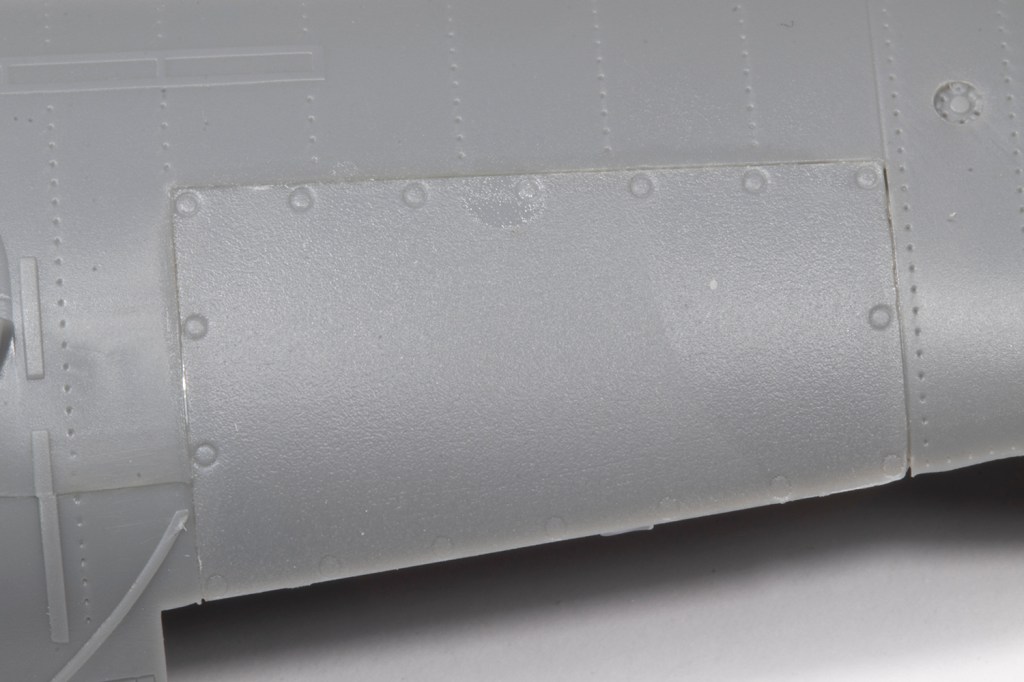
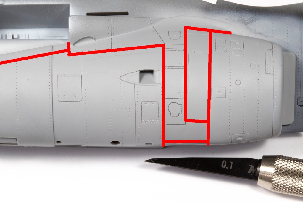
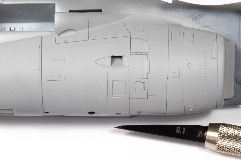
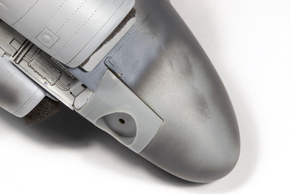
Some more comments on accuracy. Hobby Boss mould locations for lights under the main intakes, but don’t provide actual parts. These were sourced from the spares box as was a replacement for the red light on the nose ahead of the pilot (a red clear resin part from a Quickboost set for the Supermarine Walrus). For this airframe, the plinth on the nose gear door had to be removed. I think the blast plates behind the exhaust are not a very good shape (in my opinion they should be much more triangular) but this was a modification too far, and what you see is what the kit gives. Hypersonic draw your attention to some inaccurate panel lines ahead of the exhausts, and I did replace these angular lines with a nice curved panel line as instructed.
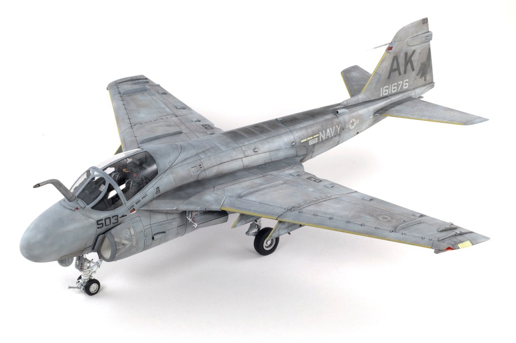
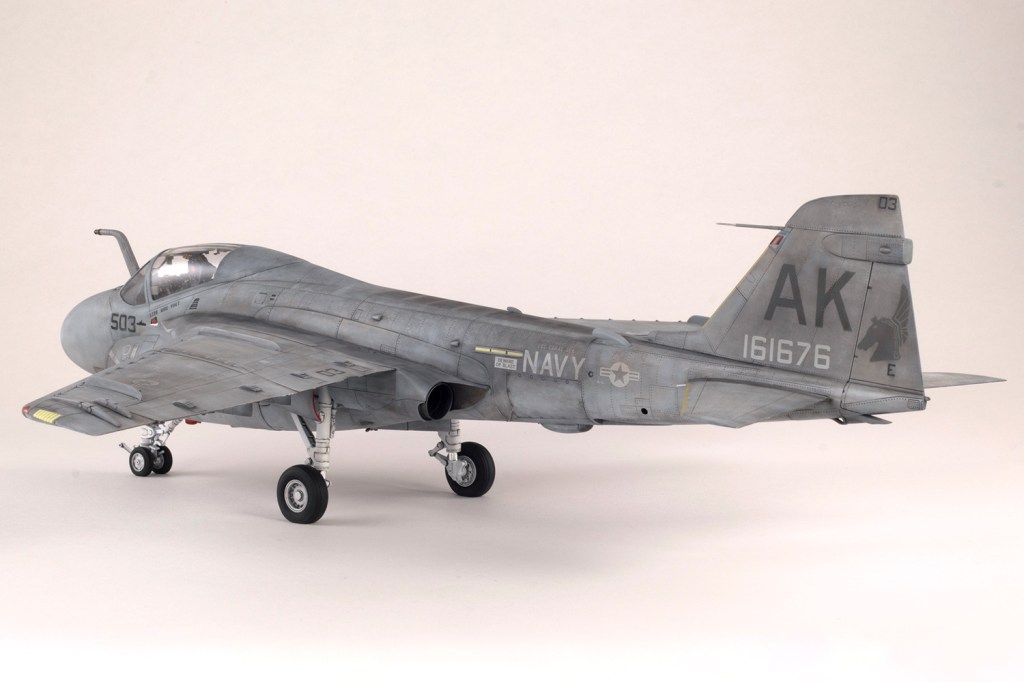
Hobby Boss provided plastic cores for the undercarriage with this boxing – earlier issues have them in cast metal. The ResKit wheels I had purchased are generic and not specifically designed for this kit, which means they don’t fit at all. I elected to make new attachment pegs from brass tube, but the wheels are still way too far out from the hubs, and thus my undercarriage looks decidedly wrong, because it is. The resin wheels themselves are a challenge as it’s very easy to remove too much material from the centre of the tyres for the separate hubs. Remove slightly less than you think you should and the hubs will fit nice and tight.


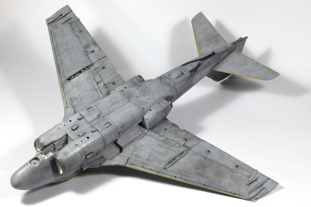
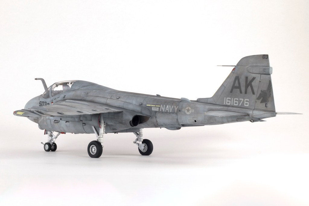
After what felt like forever, I had a big airframe ready for paint, and it really is big. I was forever banging it into things when moving it around my bench. One of the things I enjoy about constant scale modelling is the surprise of how things look in three dimensions. I’ve been looking at photos of Intruders nearly all my life, but never had such a sense of what a massive lump it was.

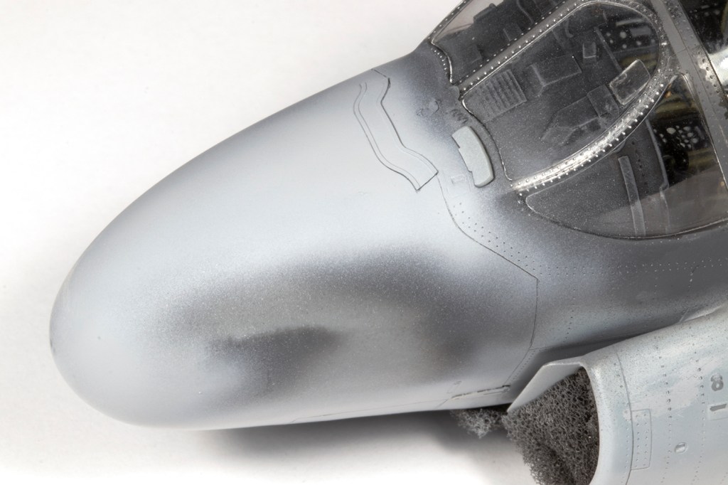
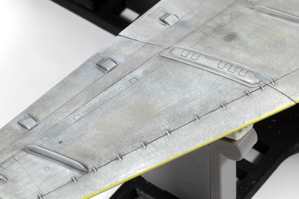
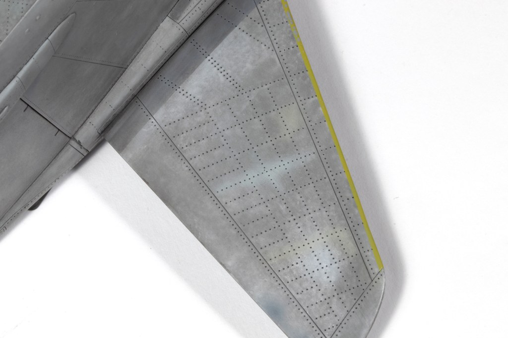
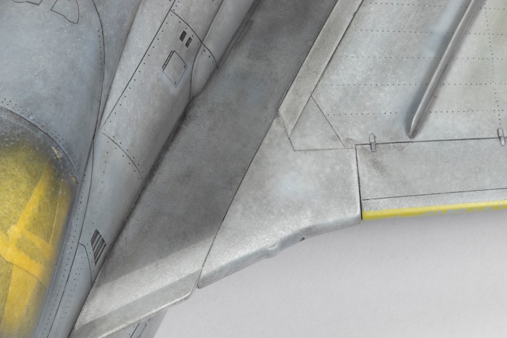
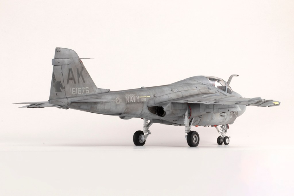
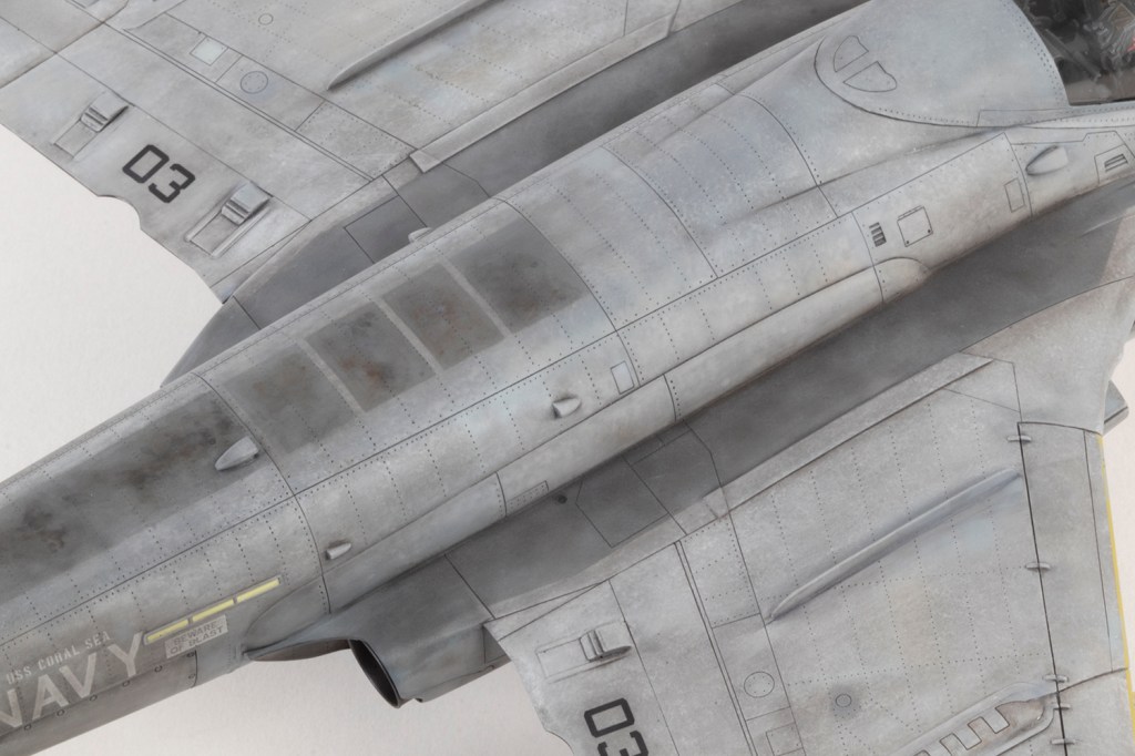
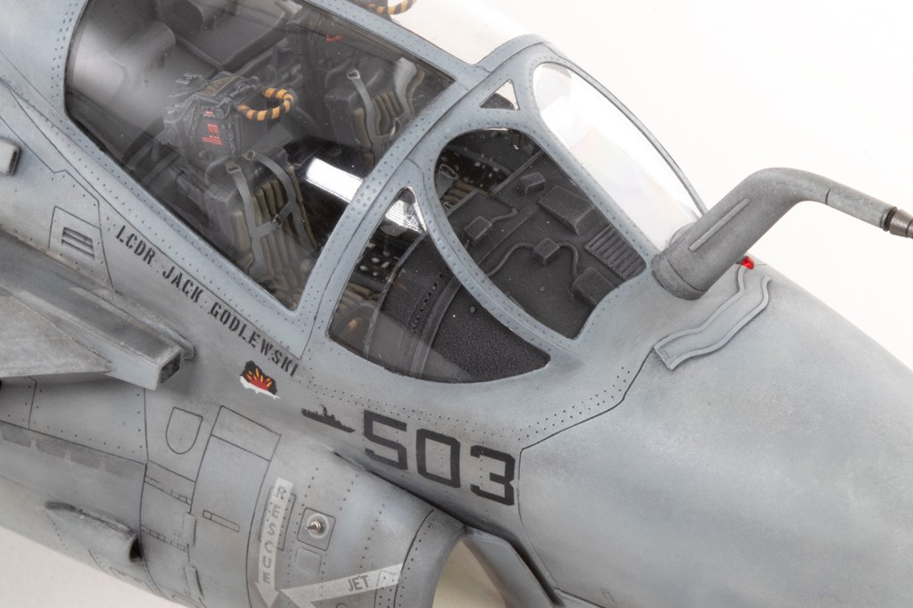
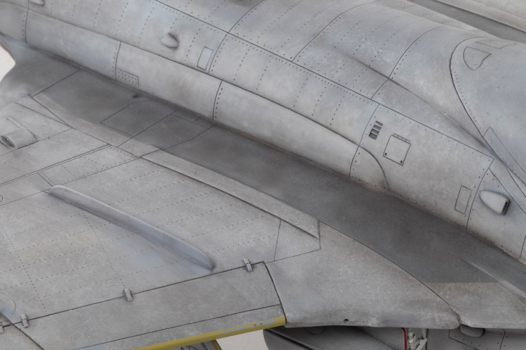
For the TPS scheme I decided to try the ‘ink patina’ method pioneered by Kris Sieber. Details are on his Luftraum72 blog, but essentially it’s a sandwich of paints and inks with the top layer removed with solvents. On the bottom was a solid coat of Mr Surfacer 1500 Gray, which when dry was moistened with Tamiya X-20A and then Liquitex White ink generously brushed on top. As the ink dries it is lightly stippled with a Deerfoot stippler brush to give a randomly blotchy finish. Over this I airbrushed very thin coats of FS36320 Dark Ghost Gray (for the upper surfaces) and FS36275 Light Ghost Gray (for the lower surfaces) from a variety of paint manufacturers. The demarcation is intentionally difficult to see, as per the real thing. The whole lot was sealed with Mr Color GX113 Super Clear III UV Cut Flat (a very complicated way of describing a matt varnish).

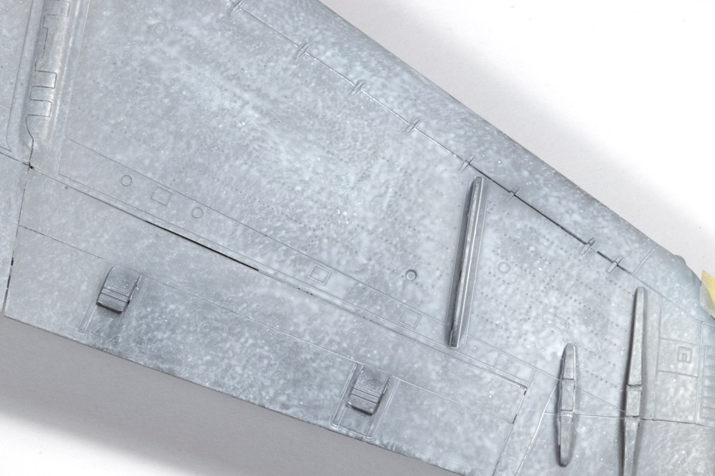

Now, over this you are supposed to moisten the surface again with X-20A and brush on a coat of dark grey Liquitex ink, which is then gently removed with cotton buds dipped in 50-70% isopropyl alcohol. I tried this and it did not work at all. The alcohol lifted the underlying paint and the dark ink was extremely difficult to remove. I tried a variety of different matt coats and differing strengths of alcohol, but still the same result. Fortunately I had not covered the entire model in this stuff, and the sides and upper surfaces were still grey, so rather than using a dark grey ink, I switched to a layer of moderately thinned dark grey oil paint. This worked wonders and gave me a finish I was very excited about. It doesn’t look great up close, but from a normal viewing distance I had exactly the kind of grotty texture I was looking for. I enhanced this by spraying small areas of the airframe with spots of different grey paints to represent touch-ups common to this kind of scheme.


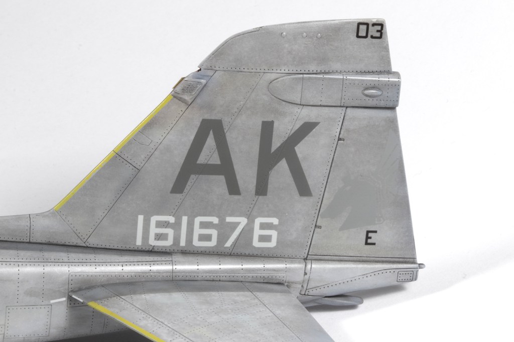
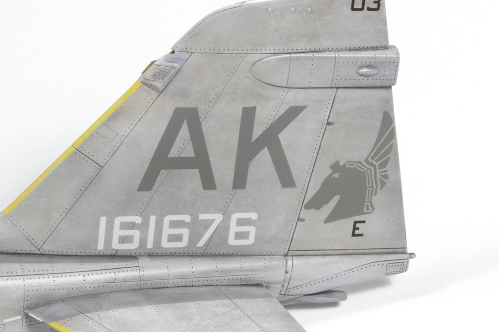
It was with some nervousness I applied the decals as (per AOA’s own warning) they can disappear if you get the painted shades of grey slightly wrong. Fortunately all was well, except when it came to the War Horse heads on the rudder. I had already painted the ‘AK’ tail code using a shade of paint (Mr Color C32) that I thought matched the decal sheet, but the winged heads were invisible against the background paint and clearly my match was not good at all. This stressed me out no end, but I managed to cut some vinyl masks for the heads using a Silhouette Cutter (depth 2, force 2, speed 1, for those who care) and overlaid them gingerly over the decals. The size is right at the limit of what the cutter can do, but with some airbrushed C32, the heads now matched the tail code and were visible against the rudder. They are too dark, but I like that they stand out.

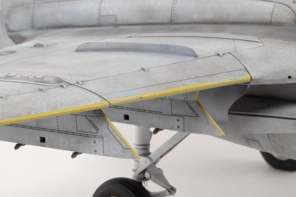
For nostalgic reasons (harking back to a Hasegawa 1/72 A-6E I made in the late 1980s), it was important to me that I model a scheme with the ochre yellow tape applied on the leading edges, in this case painted with Mr Hobby H34. This seemed to weather away pretty quicky, so I used some hairspray as an undercoat so I could chip it back. It’s a bit paler than I would like, but adds some interest to the very grey scheme. Walkways were all airbrushed on with dark shades of grey and weathered with oils, AK weathering pencils and Gunze Real Touch Markers.
The decals are beautiful, but AOA did make some mistakes they rectified in a later ‘Redux’ issue of the sheet. I stuck with their initial release, so there are a few minor errors, but hey ho.
Final assembly was a challenge, especially as the port main undercarriage leg did not want to fit in place correctly until I removed the locating peg for the actuator. I’ve no idea what went wrong here! Take your time dry-fitting the undercarriage doors and trimming the locating pegs; most of them will fit fine. Master provided the beautiful refuelling probe end and the tail-mounted pitot, which is terrifyingly fragile but looks gorgeous.
This is a complicated beast of a model. Hobby Boss have been very ambitious in the scope of what they wanted to achieve, but bit off slightly more than they could chew. If you like everything open and dropped, you will have a whale of a time, but if you like it all closed, be prepared to put some effort in. I have an A-6A that will trundle off the work bench in a couple of months’ time, but I won’t be building any more and can only hope that Mr Tamiya will furnish us with a kit I can build as an A-6B or C in years to come.


Year bought: 2024 (Ebay)
Year built: 2025 (New Addington, Croydon)
Back to home.
