10th ARS, US Air Force, USA 1948

Prior to the financial crash of 2008, the currency markets reached the giddy heights of two US dollars to the pound. This, combined with the fact I lived in China and didn’t need to worry about VAT, meant buying kits from America was suddenly a bargain. When Classic Airframes re-released their 1/48 Duck (denoted by the ‘R’ suffix on the product number), I could not resist and it winged its way over the Pacific to me at what I thought was a steal.
The Grumman J2F Duck stems from 1936 and was an evolution of the earlier JF Duck (which had a shorter float), that itself traces its roots back to the 1920s and a series of amphibian aircraft made by Loening. I only build post-war aircraft, which means I rarely make biplanes, and it would be a treat to have a plane of this design in my collection. This would, in fact, be the first biplane I’d built since I was a kid. Add that to its limited run nature, and I approached this project with some trepidation.
I bought the excellent Ginter reference book on the Duck and made use of the Squadron Mini In Action publication. These would turn out to be essential because Classic Airframes were a little confused as to what variant they were actually making.
This version of the kit is billed as a J2F-5/6 (OA-12) Duck. The OA-12 was simply the USAF designation for the J2F-6, so the real differences are between the -5 and -6. The publications tend to minimise these and simply state that the only difference between the two was the engine. Careful study of photographs shows that this is not the case.
The cowlings were different, the -5’s being slightly shorter than the -6’s. The nose sections were substantially different, with the -5 cowling sat well proud of the nose, whereas the forward fuselage of the -6 joined smoothly with the cowling and thus had a different geometry. The lower sides of the nose on the -6 flared outwards to accommodate some kind of vents. Lastly, the -5 had a large and prominent intake sat on top of the cowling which is not not present on the -6. Classic Airframes essentially give you mishmash of the two versions, and for the -6/OA-12 you will have to scratch build the forward fuselage vents yourself, and omit the intake. There are other substantial inaccuracies which I will get to in due course.
The kit is a typical limited run production from the turn of the century. My copy may have suffered from being a reissue, when maybe the moulds were more worn. There was substantial flash around the wings, significant mould misalignment on the struts, and various other lumps and bumps on the plastic, as well as what looked like artefacts from cracks in the moulds. The surface detail is petite, but inconsistent and the raised rivets with which the real thing is festooned are missing. The plastic is very soft.
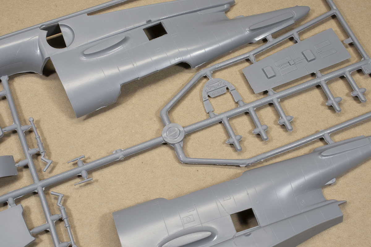


A fair few parts are moulded in pale yellow resin, mostly for the cockpit but also the engine and other assorted parts. The moulding quality varies from excellent (such as the seats) to very poor (the engine). No photo-etched parts are included, but clearly they were planned as there are location holes for non-existent grab handles and control surface actuators that Classic Airframes provided in this medium in other kits.

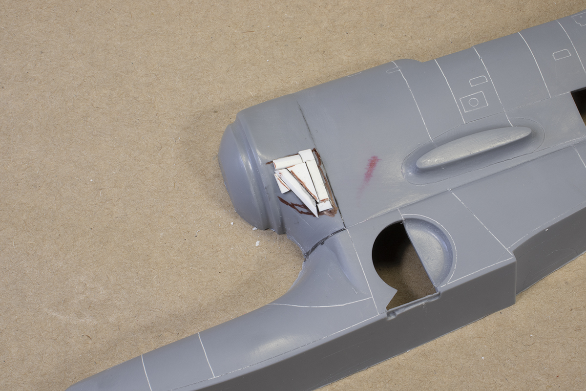
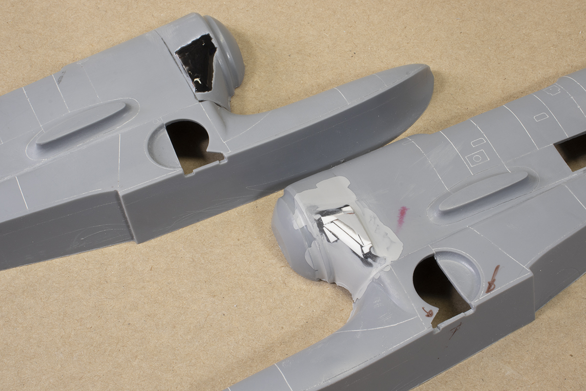
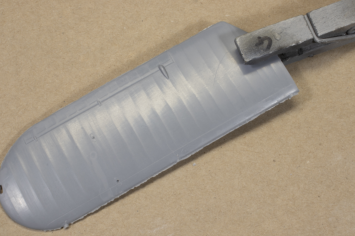
I started with the fuselage halves. The nose parts and vertical stabiliser are separate, and rather than follow the instructions, I created complete left and right halves. This was where I began to realise I needed to check absolutely everything against photographs. The nose parts were, I thought, a horrible fit. I fettled them as much as I could to try and get a smooth transition above the float. I then realised I’d made a mistake, and there was meant to be a large step at the top of the float. Fortunately enough of this step remained. It was when examining this I noticed Classic Airframes had missed the large vents on the lower nose and that I would need to scratch build these.


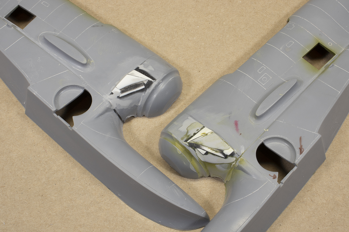
I do not like scratch building and have no affinity for it. I spent a while figuring out how to approach these, and in the end settled for a base created out of scraps of thick plastic card with the gaps filled in with a thick mix of superglue and VMS CA powder. I roughed out the shape using sanding sticks and then created an outer layer using more card and superglue to produce the lip of the vent at the aft end. I did all of this by eye and do not claim any great accuracy, but it was close enough for me. Once I had done one side, I did the other and hoped they would be symmetrical enough. Even with all this done, the nose is still not quite right: it should slope upwards at the front of the anti-glare panel to meet the cowl, whereas it’s just a straight line in the kit.


The surface detail on the fuselage halves needed rescribing. I generally used a 0.15mm scriber by Alec Holly, which is excellent for following the moulded panel lines to make them deeper. In places I used HIQ Parts guide tape, which I find more convenient than Dymo tape as there’s no backing film to remove and the tape is transparent.
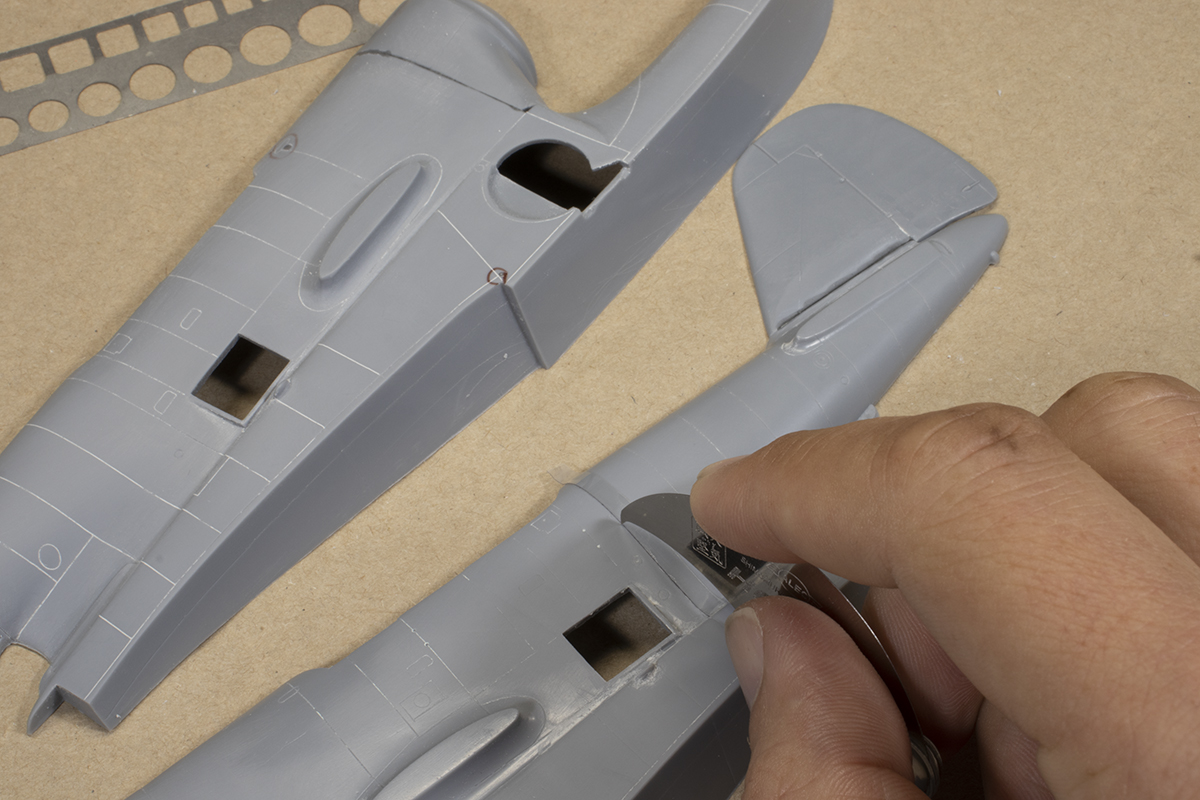
I did a lot of dry-fitting and noticed that, when the parts were cleaned up, they generally fitted rather well. In some ways I approached this kit a bit like a vacform, which set my expectations accordingly and made for a less frustrating build experience.
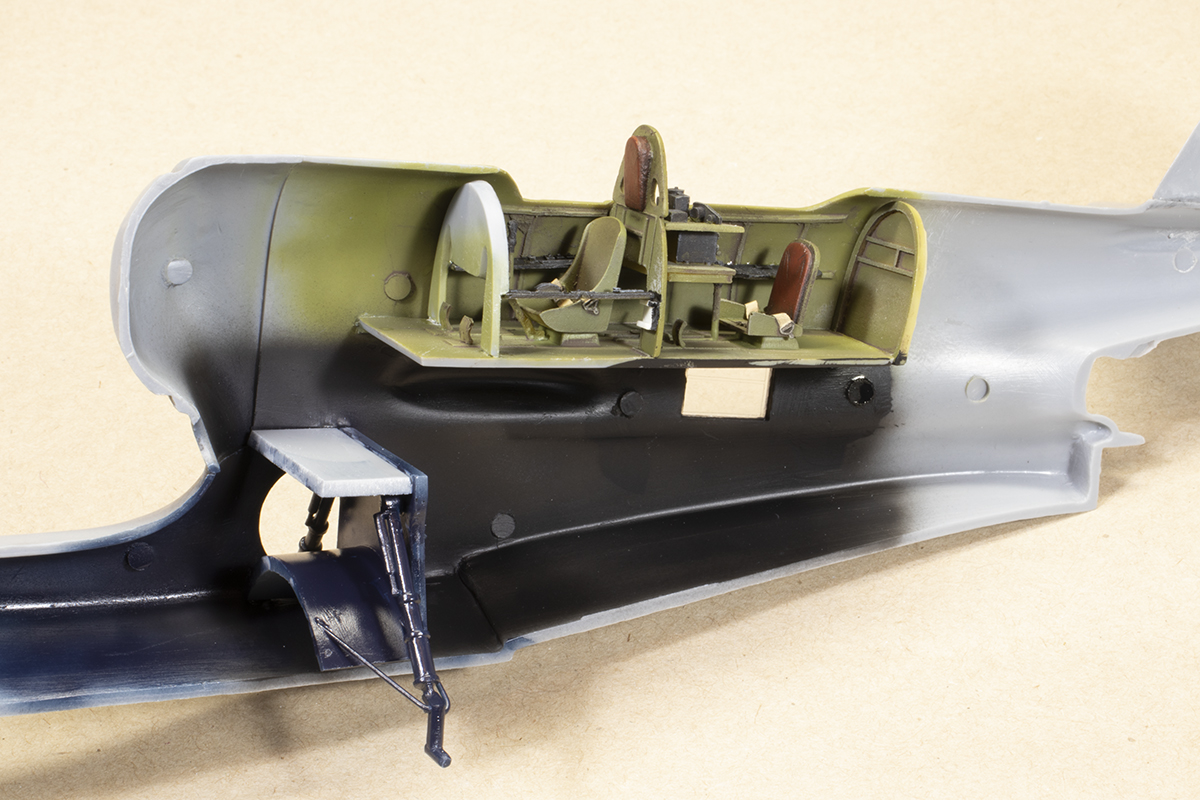
The interior looked like a challenge as figuring out how to install it was not obvious. The cockpit itself is moderately well detailed, although the instrument panel is poor and no seat belts are provided. I sourced the latter from a generic Eduard USN set and had no plans to add any further detail given the closed canopy and upper wing that would block the view. The rear seat did not look like the one shown in my references, so I’m not sure if it’s accurate or not. There is no interior included for the lower deck visible through the side windows and I would rely upon black paint and dirt to hide the lack of detail here.
One of the areas of potential stress was the undercarriage. It looks fragile and unless you are particularly creative, has to be installed prior to the fuselage halves going together. The kit provides various struts, but they are poorly moulded and the instructions recommend you replace them with plastic rod. My main goal was sturdiness over accuracy, so I used plenty of cement to attach the main legs to the internal bulkhead. This produced a surprisingly good bond that held up throughout construction. The downside is you get no chance to dry fit the whole thing and check the legs are level. I carefully measured it all out but it would transpire it would be wonky. I blame the fit of the bulkhead into the fuselage.

There are no meaningful locating aids to add the interior parts inside the fuselage halves, so this is fraught with risk of misalignment. I did manage to do some dry fitting to assuage my fears, and found it less stressful than I had anticipated. The side windows fitted surprisingly well, but unfortunately some stress fractures appeared later on in the build; I probably should have sanded down the sides just a fraction more for a looser fit.
Getting the fuselage halves together was an achievement, and I did so using super glue in order to eliminate the risk of ghost seams. It’s a high-risk high-reward strategy which trades initial fit for easier seam removal later on. I use my usual Everbuild High Viscosity Super Glue which doesn’t cure too hard. It’s worth noting that the tip of the tail cone is far too blunt, but I did not rectify this.
I was now able to take stock of how square everything was, and the results were not good. As mentioned, the undercarriage was a bit wonky, and on its wheels, the fuselage leaned to the right. The most diligent thing to do would be to rebuild the undercarriage, but I knew I wasn’t going to manage that and settled for a fudge: the left wheel would have a flat sanded in it to make sure the wings sat level.
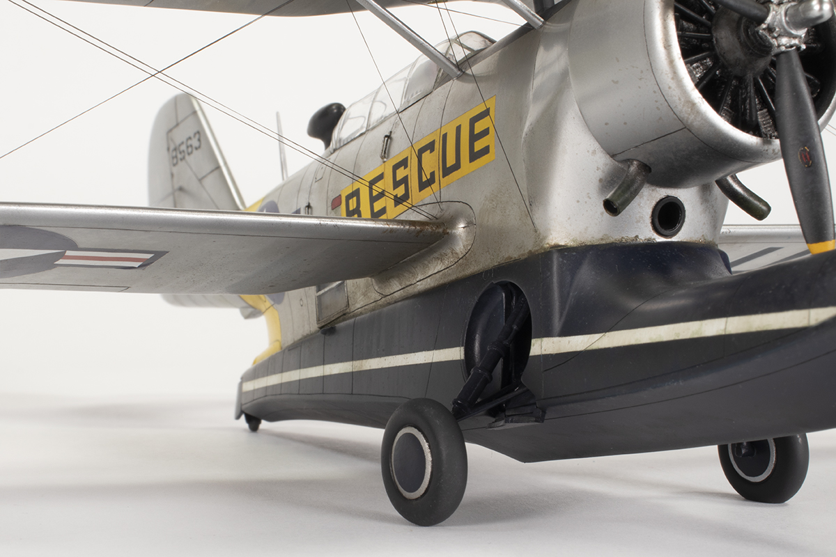
The second issue with the undercarriage was that the geometry clearly wasn’t right. If the bracing struts were to be installed, they would sit at far too steep an angle. After spending ages looking at photos, I couldn’t figure out if the problem lay with me or the kit, but in the end I decided to abandon installing the lower struts and stick with the fairly robust assembly I already had. It’s definitely a compromise on the finished article. The small undercarriage doors are poorly shaped and the wheels are not much better, but I used them as provided.

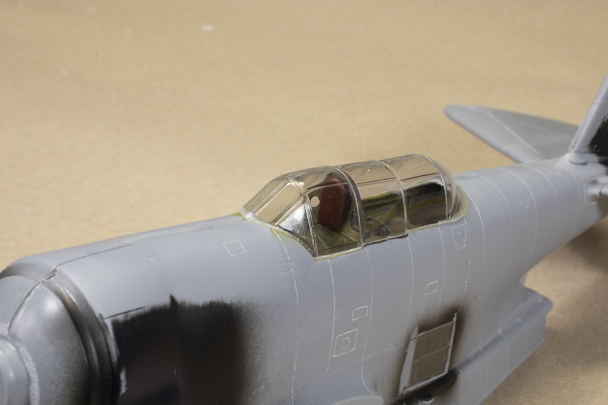
Since I could not remember the last time I built a biplane, I had to give quite a lot of thought to the order of construction. The basic plan was to finish the airframe less its upper wing and install that at the end. This meant I added the canopy a little earlier than I normally would, prior to the lower wings as these were simply a butt joint and would get in the way of clean up.
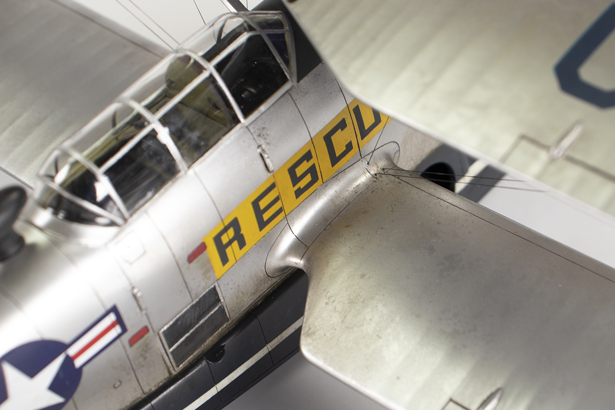
The initial fitting of the canopy was disappointing as it would not go down over the pilot’s seat bulkhead. I had to remove a lot of material from the interior part before the transparency would seat properly, but eventually it did, and did so rather well. Multiple applications of very thin Mr Surfacer 500 made using a fine brush and capillary action to smooth the transition from the windscreen to the fuselage. Once hardened, I used very fine sanding grits to slowly refine the joint.


Another area requiring attention was the circular port between the fuselage front and the float. Because the seam here was quite substantial and the kit moulding not great, I decided to use some Evergreen plastic tubing (4.8mm diameter) to obtain a decent circular cross-section. I installed it with super glue and sanded it all flush. Once done, a fine slice of the same tubing provided the protruding collar. There should be some horizontal vanes within this part, but I did not fancy making them.

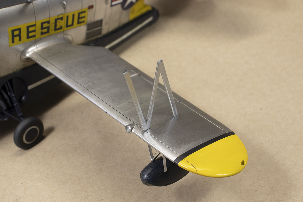
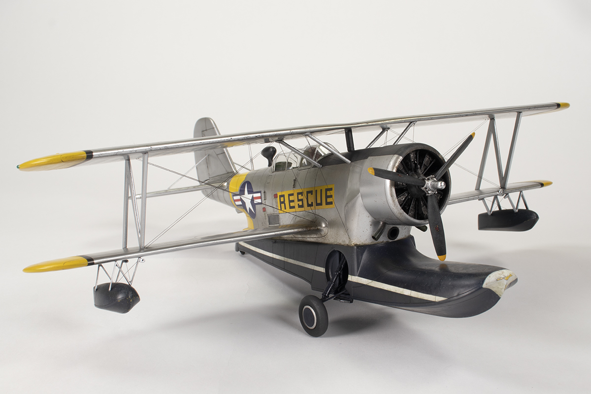
I was learning to scrutinise every area of the kit before dealing with it and take nothing for granted. For example, the wing struts have small locating pegs and matching dimples in the wings, but nothing to inspire confidence. I replaced the nubs with small discs punched from plastic card and drilled matching holes in the wing surfaces. The struts themselves were quite poorly moulded, especially those for the wing floats. I never really cleaned them up to my satisfaction but didn’t have the nerve to replace them from scratch. Whilst examining the struts, what also became obvious was that Classic Airframes have omitted the vertical strut from the nose to the upper wing. It’s not on every Duck, but on the vast majority and definitely the one I was making. It’s easily visible on the box art and I used a part from the spares box (which once belonged to an Academy MH-60 kit) to fashion this part. It’s overscale, but I wanted something fairly substantial for the upper wing to join to. I used some plastic rod to pin this and the cabane struts to the fuselage which allowed me the chance to dry fit them later on.

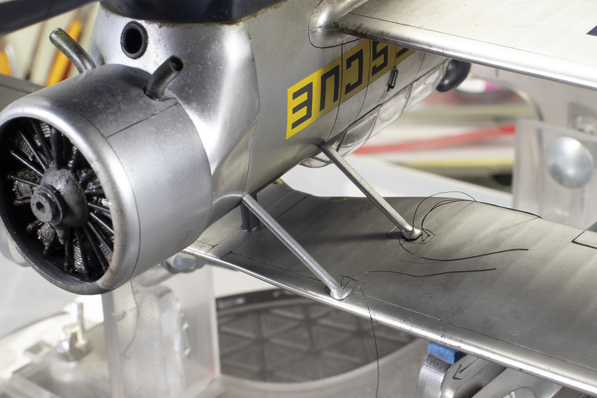
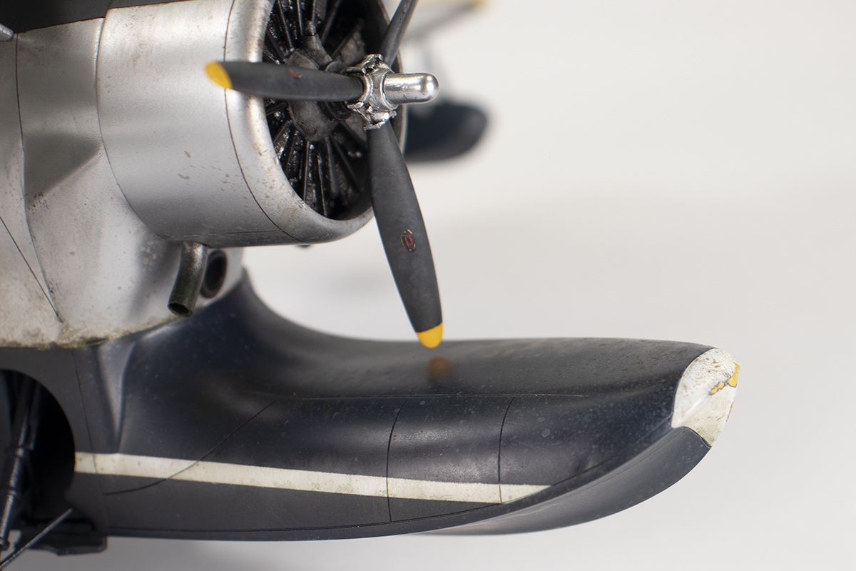
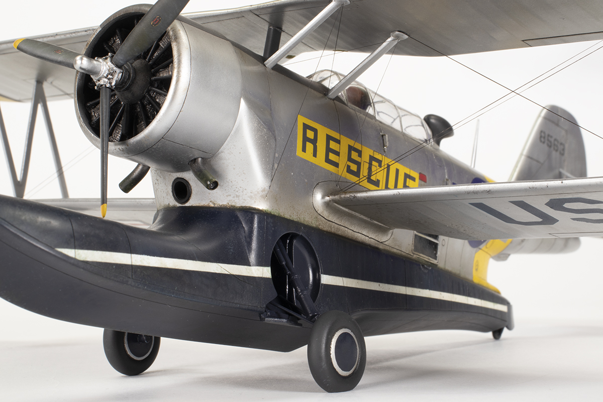
The resin engine is one of the weaker areas, being poorly detailed and with lots of moulding defects, like some missing push rods and various air bubbles. I should have replaced it really, but stuck with the kit part and some new push rods made from plastic rod and brass tube. The resin prop boss needs swapping for the plastic one (not mentioned in the instructions). I could not get the exhaust parts to fit at all, and resorted to cutting the ends of off and just sticking them in the holes in the cowl later on. They are also ripe for replacement but I made do by just drilling the ends out.

I always try and read other articles on the kit I am making to get some warning of potential issues. One that I was alerted to, and would probably not have seen myself, is that the propeller blades are much too long; long enough that they collide with the float! Fortunately there is some room at the prop base to remove enough material. I did this by marking out a line with tape and then using a file to slowly remove material whilst rotating the blade. This created a peg which I could chop down to fit in the hole on the spinner.


After making several other modifications, such as removing the hole for the cowl intake and adding some grab handles on the fuselage from scrap brass, it was time for the next major step: the wings. I toyed with the idea of pinning them to the fuselage, but in the end decided to put my faith in glue alone, and stuck them on with Tamiya Extra Thin and filled the gaps with superglue. They have not come adrift yet. I like to do this sort of work on a baking tray as it allows me to use magnets as jigs along with Blu-Tack to get everything square.


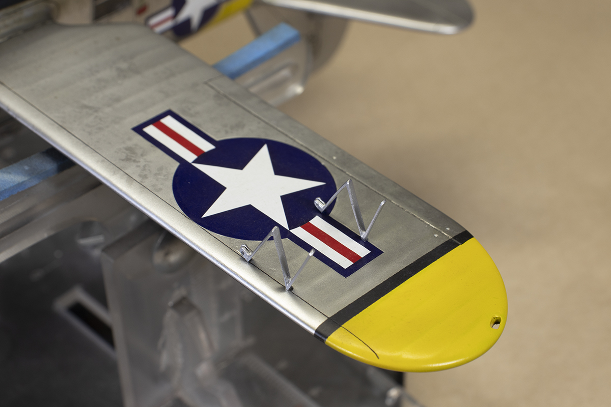
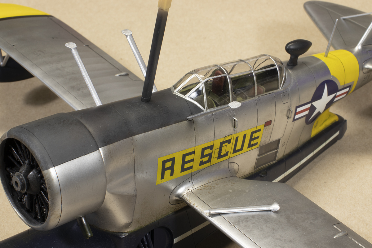
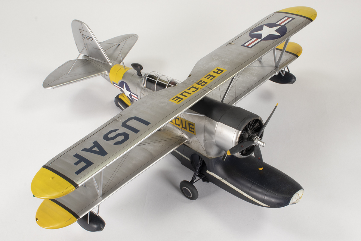
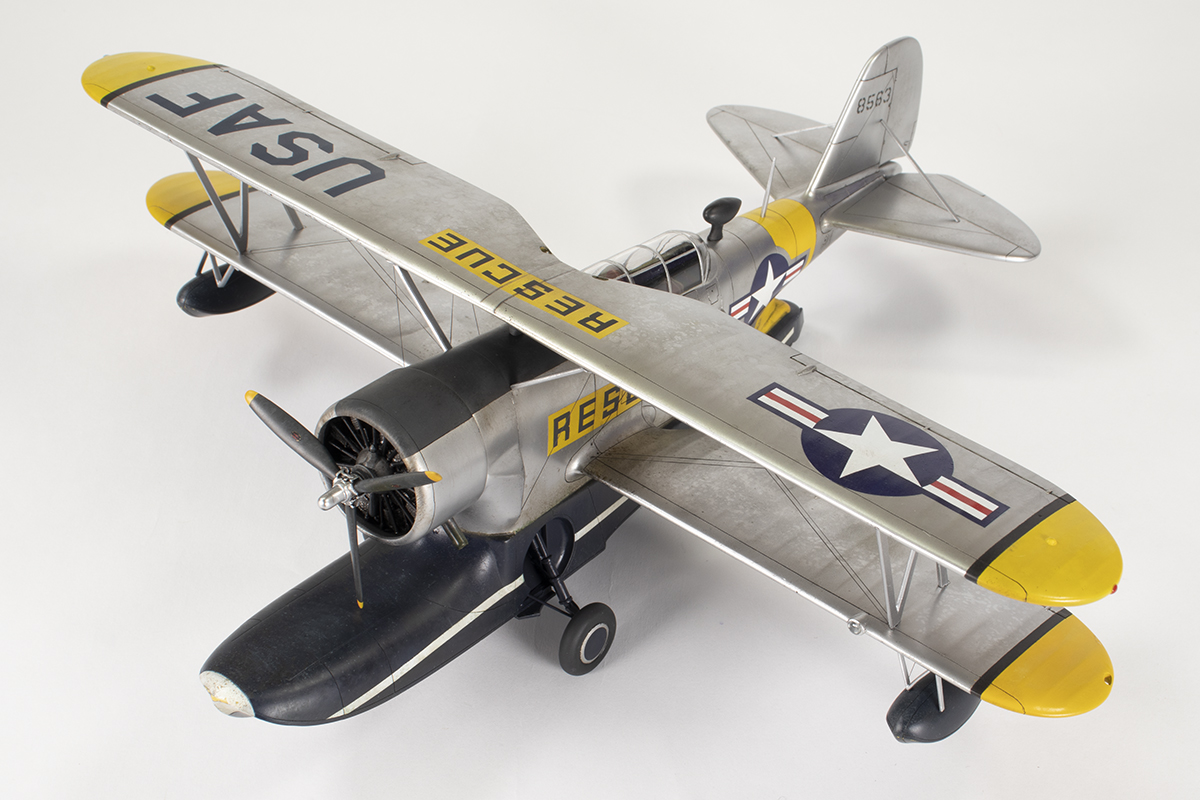
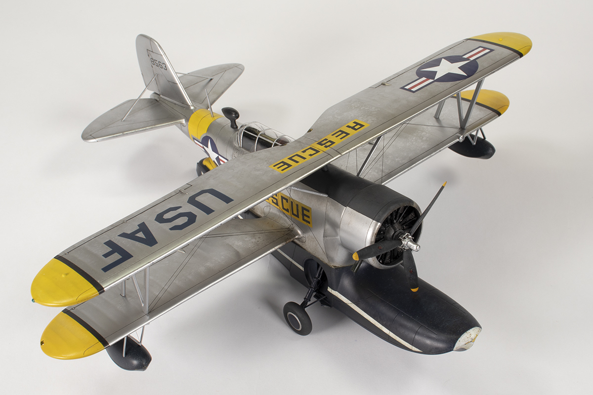
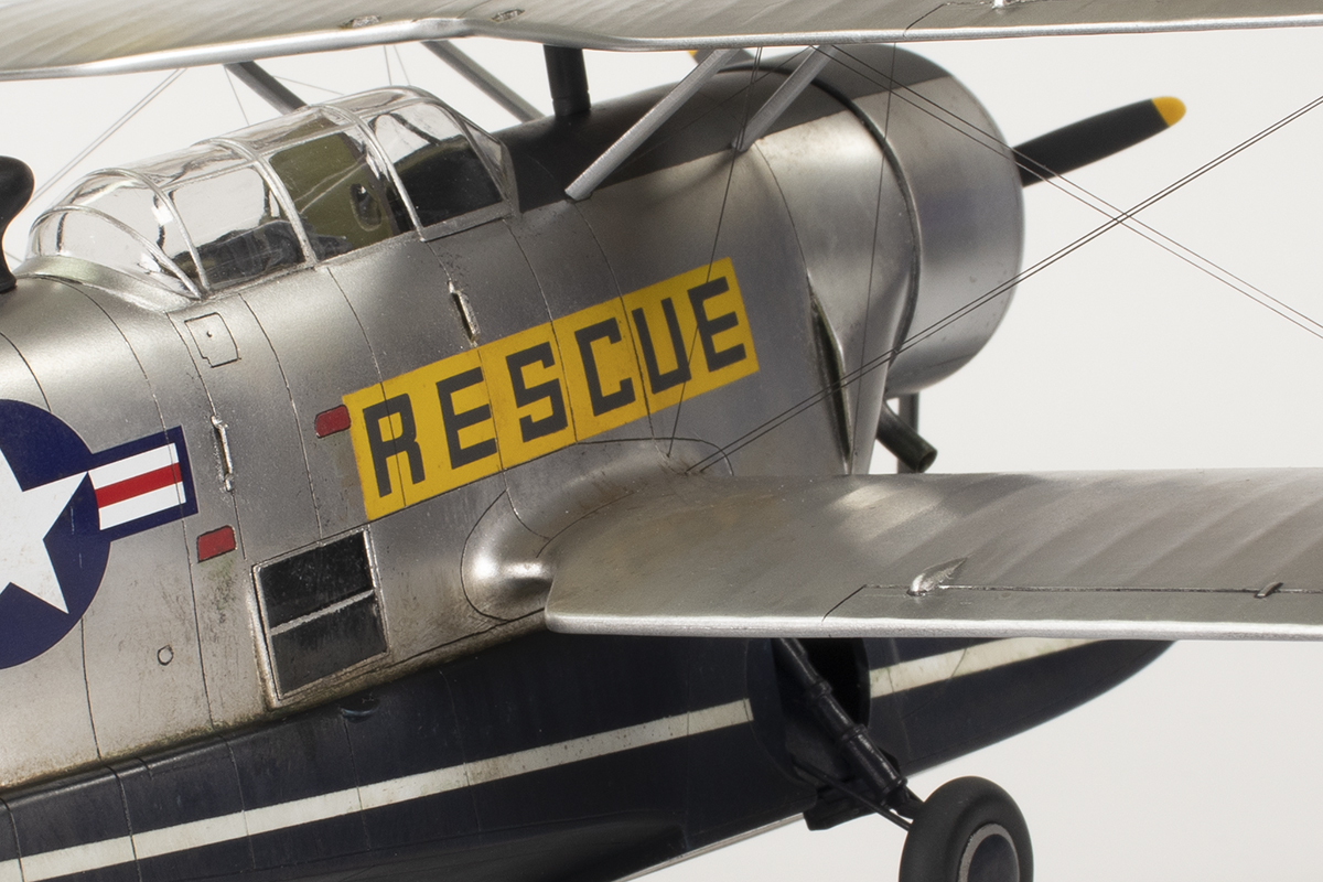
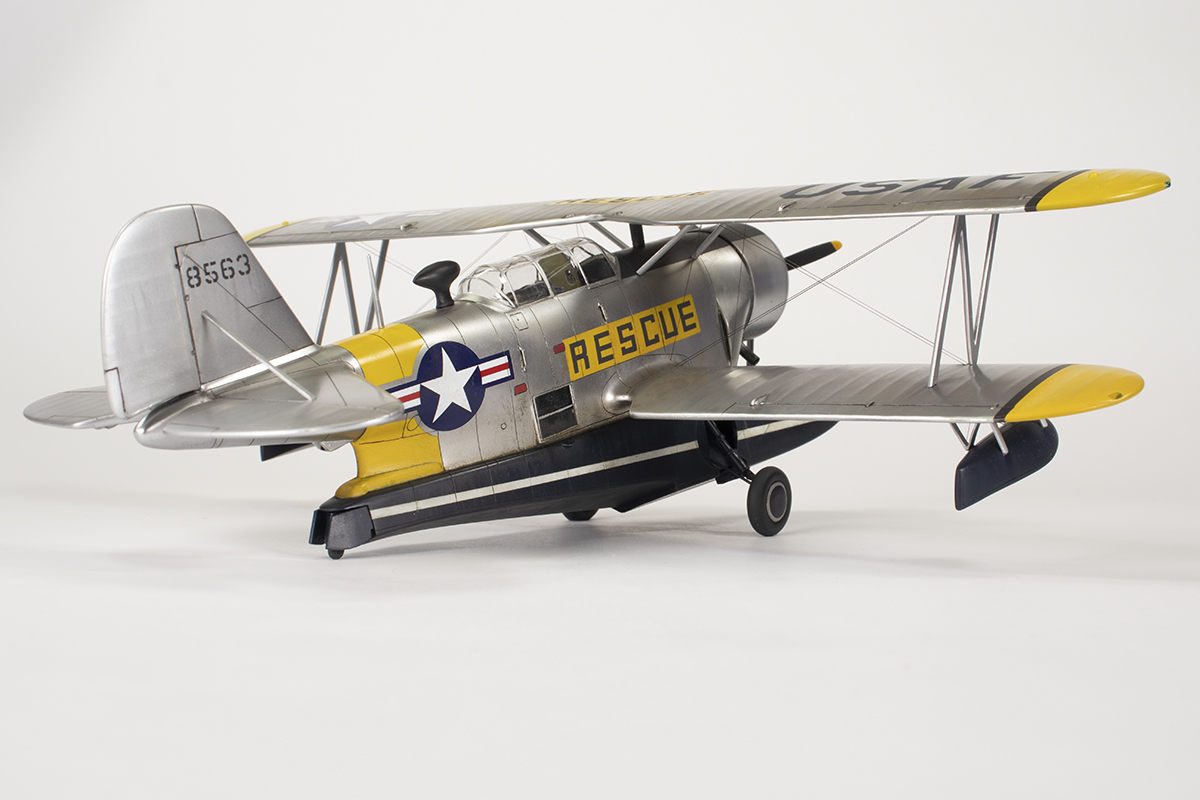
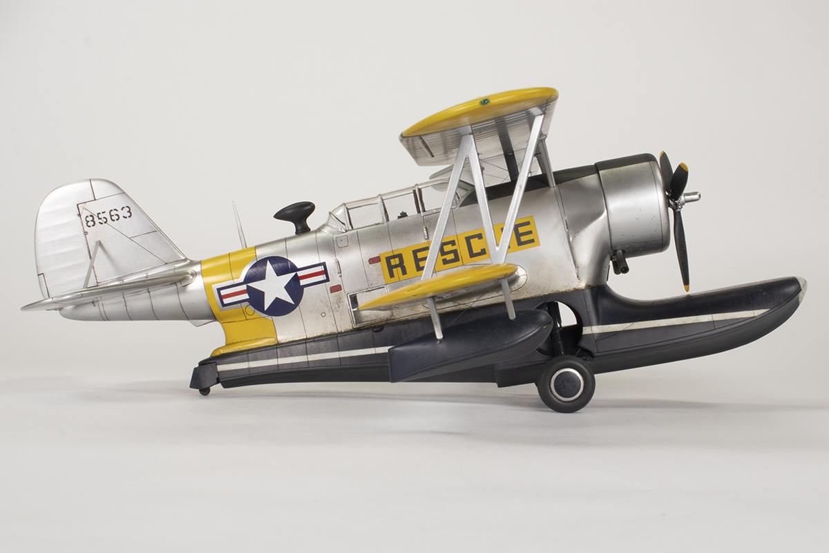
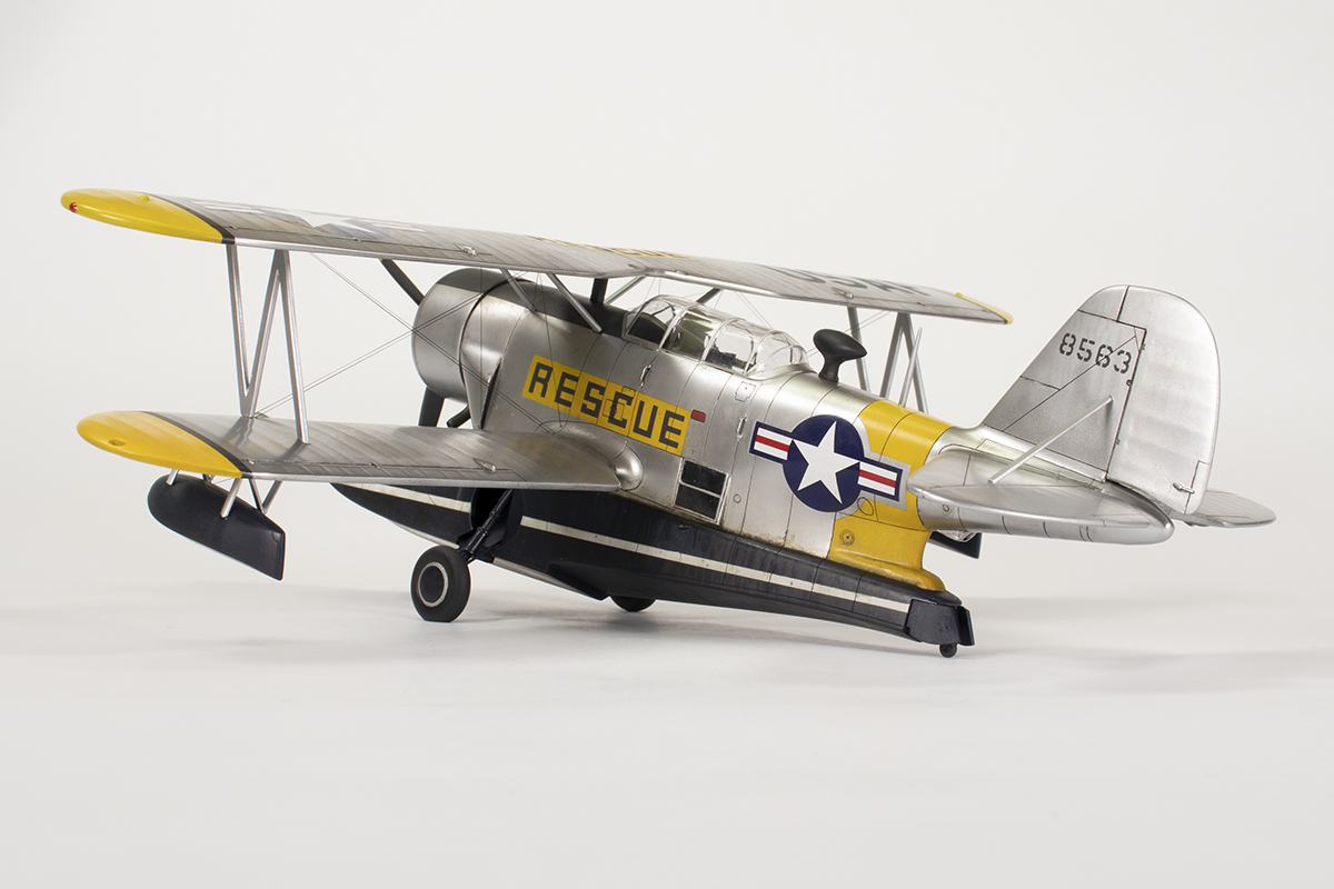
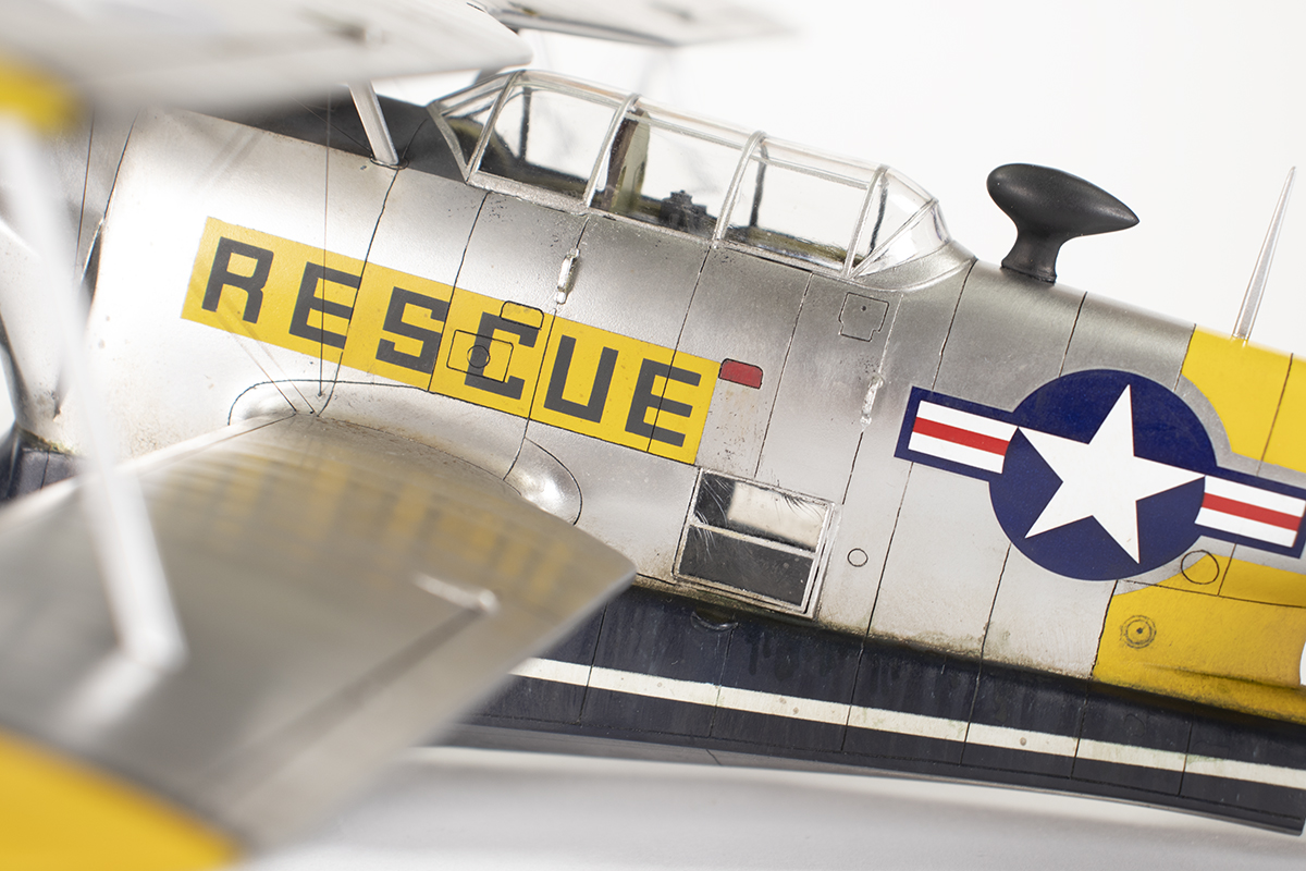
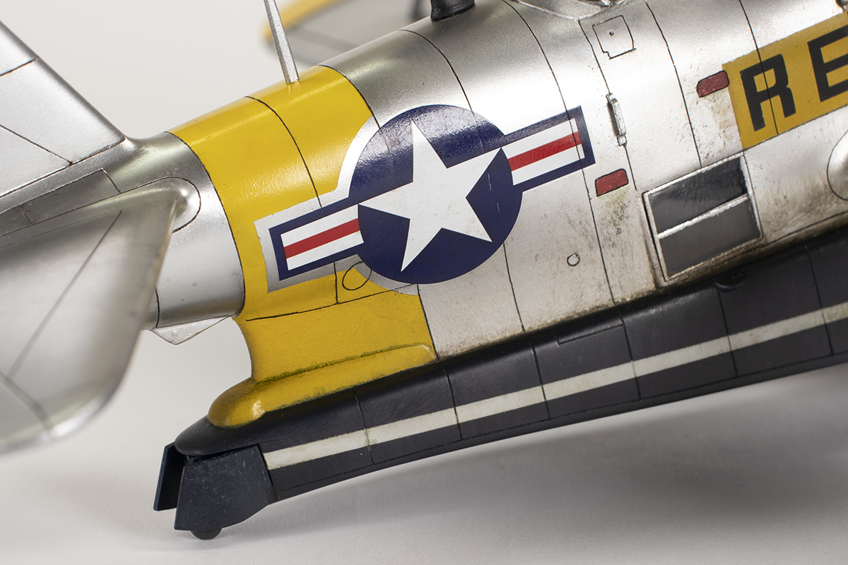
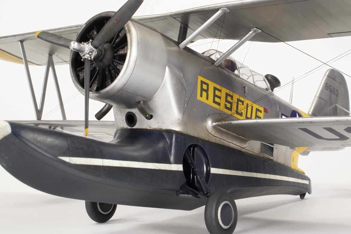
With the wings on I turned my thoughts to paint. I had given a lot of thought as to what scheme I wanted to finish this aircraft in. The kit provides markings for 48563 in a silver finish with large areas of red on the wings and tail and a dark blue float. This scheme is quite well documented, but I was more intrigued by a photo in the Squadron book of this same airframe in silver and yellow with large RESCUE markings in a non-standard font down the sides. It pays to be careful when looking for images of this scheme, as the original airframe has been restored in these colours, but another has been painted in this exact scheme at the National Museum of the US Air Force, with the main significant difference being the colour of the wing floats – blue versus yellow. I can’t speak to the accuracy of them being yellow at some point, but the photo of the original clearly shows them to be dark, so mine would be dark blue to match the main float.
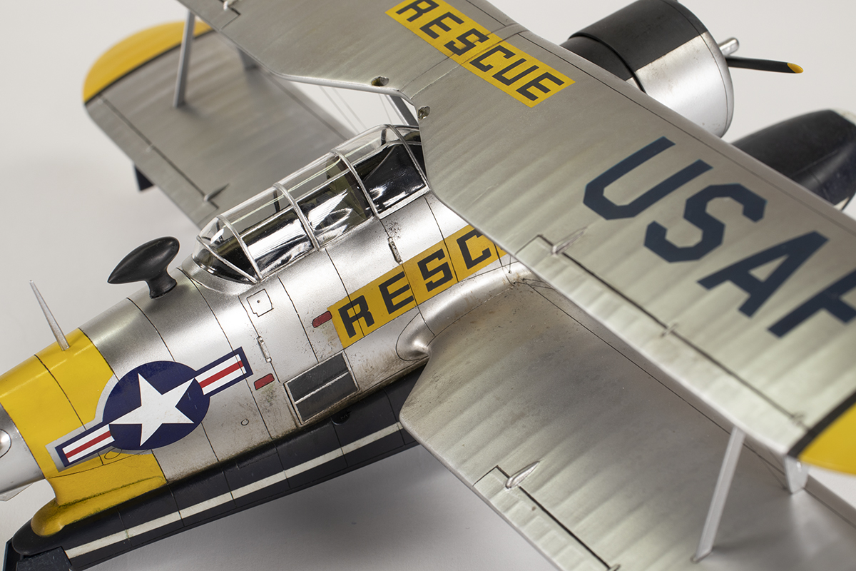
This scheme would also require some speculation as I had no view of the wings. I decided to add the RESCUE legend to the centre of the upper wing and the USAF markings in the usual place (practices followed on the similarly marked OA-10 Catalinas).
Doing all this would mean designing masks in Inkscape on my computer and then using a Silhouette cutter to cut them out. In the end the only decals would be the kit stencils on the prop blades and national insignia from a Furball sheet. Without a decent profile view I had to make some guesses in relation to the dimensions of the RESCUE boxes, but compared to the photo I’m satisfied it’s close enough.
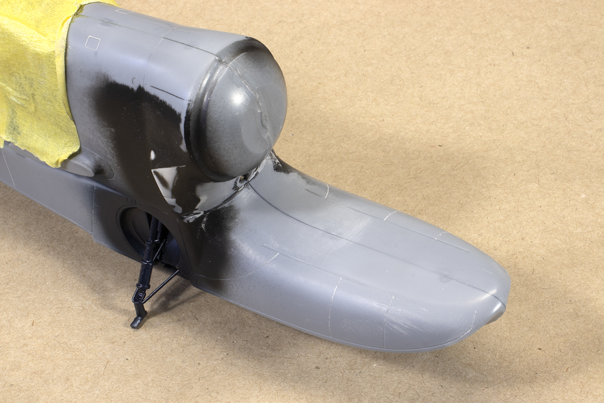
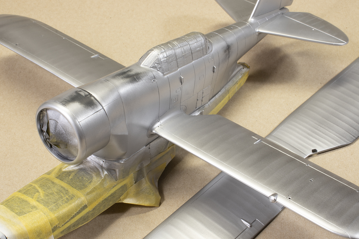
Armed with all this information, it was time to start throwing paint at the model. I’m a firm believer in priming just to make sure there are no surprises when the topcoat is applied, especially with a kit as rough as this. I use Mr Finishing Surfacer 1500 Black quite heavily thinned and sprayed on thick and wet with an Iwata RG-3 mini spray gun. After rubbing down various imperfections, a top layer of Mr Color GX2 Gloss Black was applied in a generous layer to make a decent foundation for the Alclad to come later. The base coat for the float was Mr Color 326 Insignia Blue, over which I sprayed some MRP-300 Insignia Blue through a mottle mask, just to get some variation in shade and patina. I cannot be sure the tip of the float was white, but both restored airframes used this colour and it’s a good match for the black and white reference photo I was following. The white stripe was painted next as I find it easier to mask this way round.


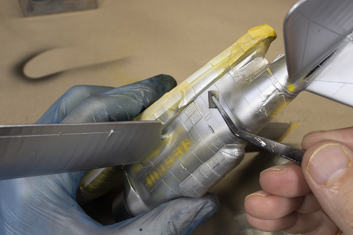
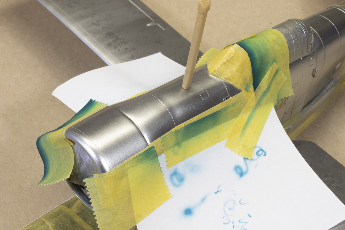
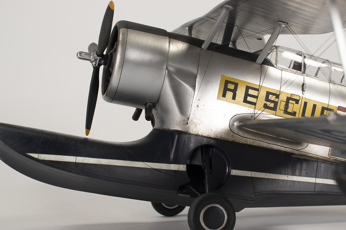
The real thing was not natural metal, so I was not especially bothered about getting something that looked metallic. Alclad White Aluminium formed the basecoat before I started with the markings. The wing tips, tail band and RESCUE boxes were all to be yellow, and I wanted quite a bright shade. For this I chose Mr Color 4 Yellow with some mottling using MRP-122 RAF Marking Yellow. I use paper versions of the masks to get the positioning correct and then applied the vinyl masks and Tamiya tape to protect the yellow areas.


Next up was more silver. I decided to give Mr Color SM206 Super Chrome Silver 2 a go, since I’d recently bought it. In retrospect this was a bit of a mistake as it’s far too shiny for what I wanted to achieve, but it is beautiful paint. However, I found it can go gritty very quickly over anything but the smoothest gloss. The yellow areas I’d already painted were matt to semi-gloss in finish and this seemed to provide plenty of nucleation sites for grittiness that snowballed out of control. The solution to this was to use small pieces of very fine 2500 grit Infini sponge to sand out the texture and reapply. Because the paint dried very quickly, I could do this within minutes of applying the silver and then reapply it. The main problem was that I could not get as close as I’d like around the grab handles, canopy and top of the float, and so these areas are much rougher than I wanted.
With the silver down, the Tamiya XF-69 NATO Black was used for the RESCUE lettering. I prefer to use Tamiya paints for masks as I find they separate cleaner; lacquers can sometimes chip along the vinyl mask edge. The black striping for the wing tips was MRP NATO Black and I debated whether to add this to the yellow fuselage band. The restored airframes have it, but I could not see it on the reference picture and so decided to make life easier for myself and omit it. The USAF markings are in Insignia Blue; again speculation, but common at the time.
I approached the anti-glare panel and props in the same manner, as I wanted a multi-layered finish. The base was MRP Black over which I applied a layer of hairspray. The next layer was Tamiya NATO Black, then more hairspray, and finally a layer of Tamiya XF-85 Rubber Black. A stiff brush soaked in water was then used to scrub away at the Tamiya layers to get a more complex finish. It’s quite subtle, but I like it.

With all the paint applied, the seven decals could be applied (stars ‘n’ bars and the prop stencils) prior to weathering. The bulk of this was done with oil paints used in a variety of ways. I flicked a lot of it around the nose area and on the float to try and give the impression this lived in an aquatic environment. More oil paint was built up at the junction of the float and fuselage to give a grungy appearance where water might collect, and some was stippled around the folding step areas and grab handles. The panel lines were filled with Tamiya Black panel liner and the excess removed with a thinner-soaked fine brush. I really dislike weathering and generally try and get it over and done with as soon as possible.
This aircraft needed a football antenna on the rear fuselage spine, which is shown in the instructions but not provided in the kit. Mine was from a Revell C-47. I also convinced myself I could see another antenna mast behind this (it was pretty common on late Ducks) and so added one (this time from a Hasegawa Corsair). I assume these antennae are the reason no aerial wires were visible on the real thing. Also added around the same time were the tail bracing struts (far too short – they should fit much higher up the tail), the tailwheel (shown fitted backwards in the instructions), and the tail wheel doors (which are not the right shape).

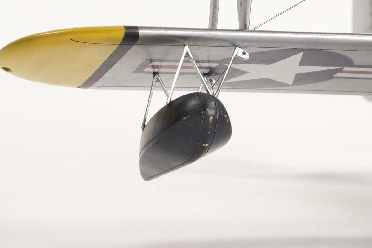
Now I had no choice but to embark on the stages of this model that really scared me: struts. There are no locating pegs for the float struts, but a few dimples in the wing surface. There’s no way to dry fit all this, so with the model upside down I simply glued them in place using tiny amounts of Tamiya Extra Thin and set them vertical by eye. I then waited 24 hours and reinforced the joints with small amounts of super glue. I could then drop the floats on top and assess the fit. Not perfect by any means – they didn’t line up with the location dimples on the floats in several places – but better than I was hoping for. With the floats resting in place I attached them with small dots of super glue. I was surprised at how level and square everything was.
I then decided to rig the floats as they would be hard to access later and it would be a good place to practise. I used Uschi van der Rosten standard gauge rigging wire, which is still too fine compared to the real thing, but I think underscale is good when it comes to this sort of detail. As this product is elastic, I needed to cut it short. I used pieces of stretched sprue to measure the lengths I would need since it can be easily held in place and cut down to size.
I started off using some gel super glue as you can put tiny wisps of it in place very precisely, but the line would not stick to it. I subsequently found out the gel glue cures from the outside in, so it has poor ‘grabbing’ qualities for this sort of thing. I switched to dots of regular super glue and found this far less frustrating. Painting some CA accelerator on the end of the line prior to placing it in the locating dot of super glue also helped a lot.

With that out of the way, I moved to the upper wing. I could place the cabane struts temporarily in place and then I glued the main N struts to the lower wing, set them vertical and hoped for the best. I used Tamiya Extra Thin so they’d have some movement at the joint when test fitting the upper wing. After waiting a day or so, I attempted to add the upper wing and…was nicely surprised. Everything seemed square and parallel and the cabane struts would fit okay. I permanently added the upper wing to the N struts, which did require some gentle force to try and get the joints to close fully. It’s not perfect, there are some gaps, and I had to feed a little CA into a few places, but it will do. The cabane struts could then be glued in place (note that the instructions show them upside down). It was very stressful, I wish it was better, and I wouldn’t want to do it again, but the result is better than I thought it would be.


The final step was the rigging, which was applied as described above. I had drilled some location holes during construction for where the lines should go; there’s nothing provided by Classic Airframes. I wish I could apply smaller dots of super glue – that’s something I shall have to practise. I worked from the inside out and again, for my first effort, I was pleased enough. There are some details missing, such as the little rods where the main bracing wires cross, but I did not want to push my luck and left it as it is.

Rather like making a vacform, you know when you embark on a Classic Airframes kit that you will be in for a lot of work and the end result is unlikely to match a well-produced mainstream kit. Nevertheless, sometimes you have no choice. This model was a lot of work and it’s somewhat rough around the edges, but it was an enjoyable challenge and I’d happily do it again, which is just as well since there are several more CA kits currently lining my loft!


Year bought: 2007 (Roll Models)
Year built: 2021 (New Addington, Croydon)
Back to home.
